Circular waveguide
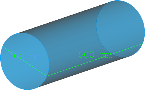
The present example considers a circular waveguide.
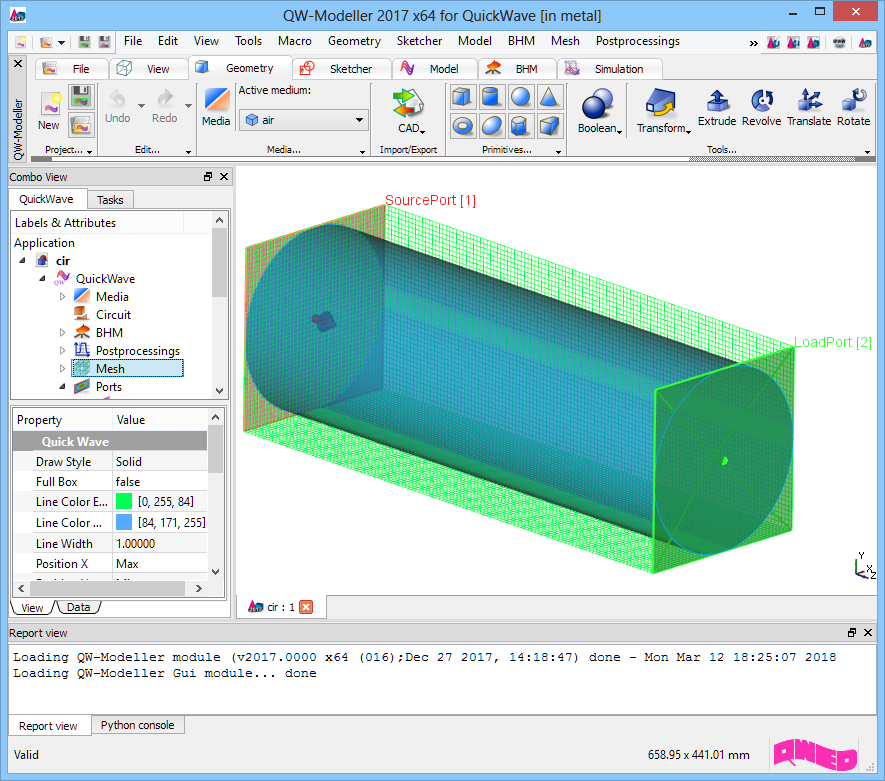
Circular waveguide project in QW-Modeller.
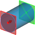
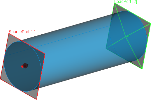
Simulation model presents circular waveguide excited with a fundamental TE11 mode (red transmission line port) and terminated with a load port (green transmission line port) matched to the waveguide. The waveguide is filled with air.
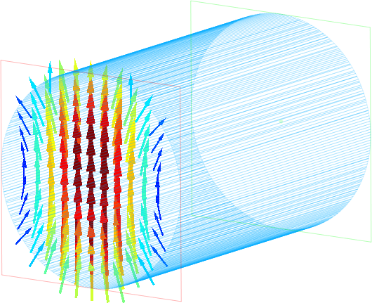
Fundamental TE11 mode at the input port - total E field and total H field.
Total E field distribution for TE11 mode along circular waveguide.
Total H field distribution for TE10 mode along circular waveguide.
TM01 mode
In the second case, simulation model presents circular waveguide excited with a TM01 mode.
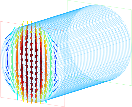
Fundamental TM01 mode at the input port - total E field and total H field.
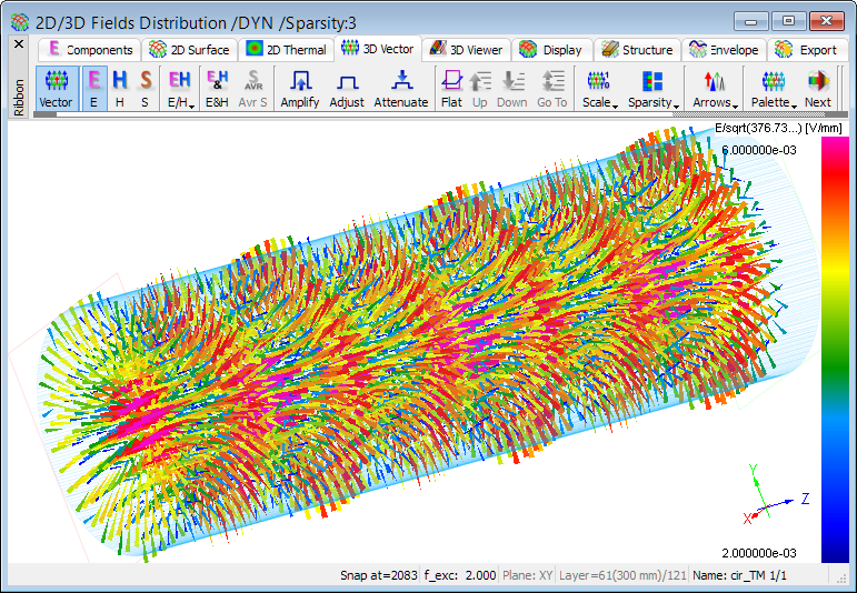
Total E field distribution for TM01 mode along circular waveguide.
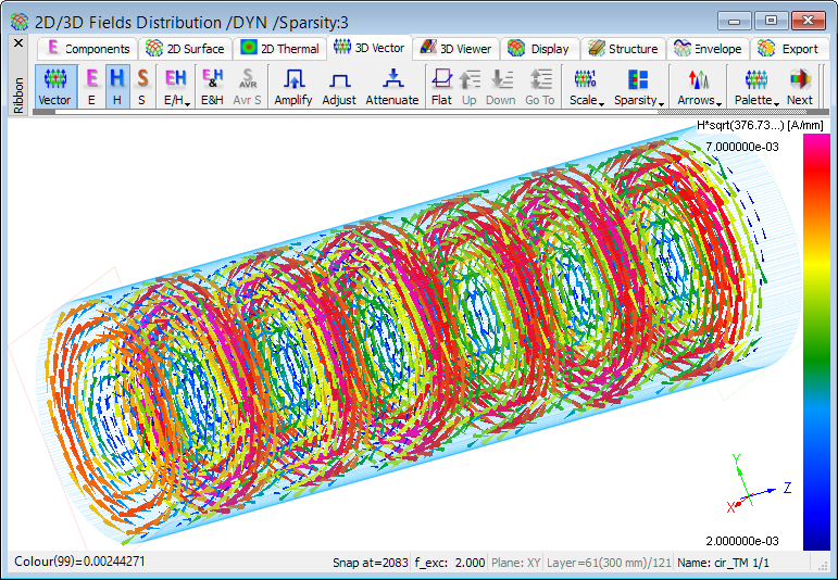
Total H field distribution for TM01 mode along circular waveguide.
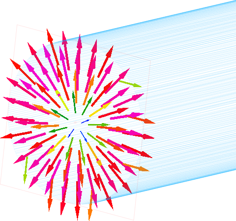
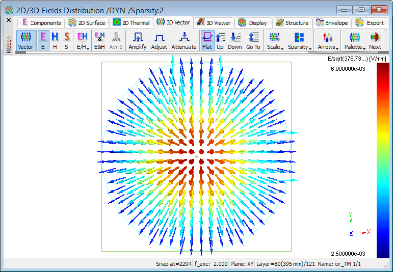
Vector display of electric field distribution for TM01 mode in a cross section of circular waveguide (YX plane - in the middle of waveguide’s length).
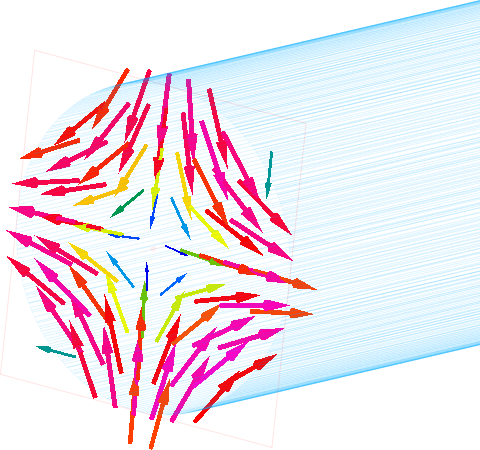
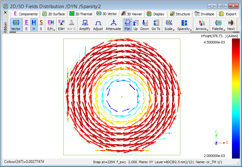
Vector display of magnetic field distribution for TM01 mode in a cross section of circular waveguide (YX plane - in the middle of waveguide’s length).
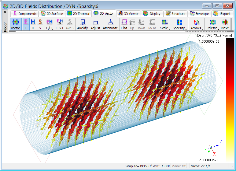
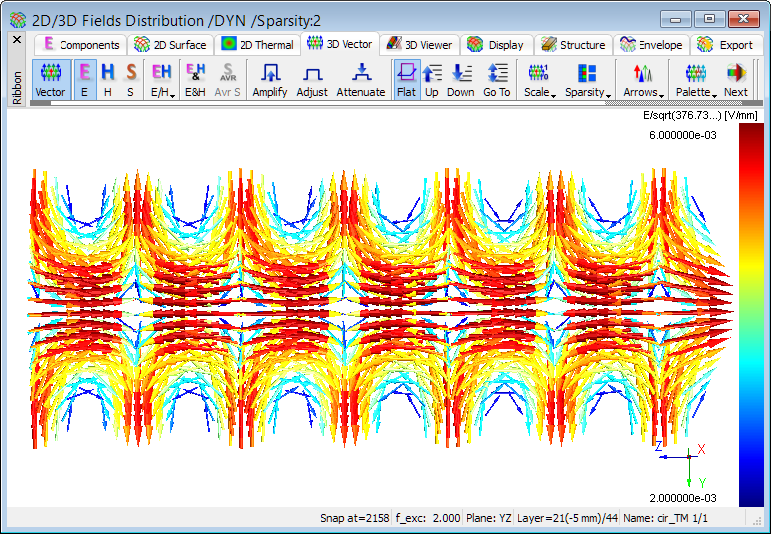
Vector display of electric field distribution for TM01 mode along circular waveguide (ZY plane - in the middle of waveguide’s width).
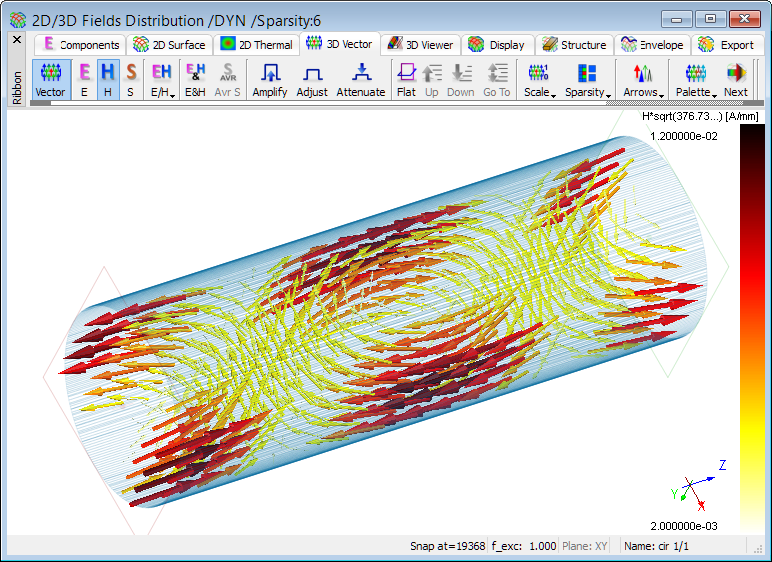
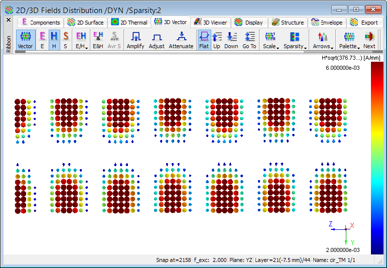
Vector display of magnetic field distribution for TM01 mode along circular waveguide (ZY plane - in the middle of waveguide’s width).
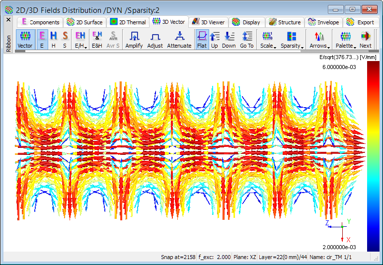
Vector display of electric field distribution for TM01 mode along circular waveguide (ZX plane - in the middle of waveguide’s height).
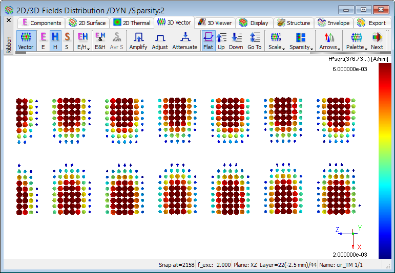
Vector display of magnetic field distribution for TM01 mode along circular waveguide (ZX plane - in the middle of waveguide’s height).