Two-reflector Cassegrain antenna (V2D BOR)
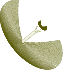
The present example considers an axisymmetrical two-reflector Cassegrain antenna (V2D BOR).
Two-reflector Cassegrain antenna (V2D BOR).
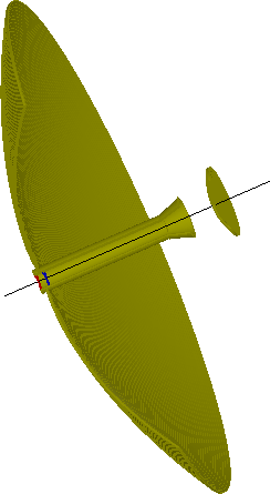
The structure that is analysed herein is an axisymmetrical horn antenna. Axial symmetry allows for performing the antenna analysis with ultra-fast vector 2D Bessel and FDTD hybrid solver (V2D BOR) designated for Bodies of Revolution (BOR) structures. This solver allows for analysing only half of structure's long-section, which results in its extremely fast performance. The structure should be drawn in a way that its symmetry axis coincides with project symmetry axis ρ=0 (in the QW-Editor and QW-Simulator referred as y=0).
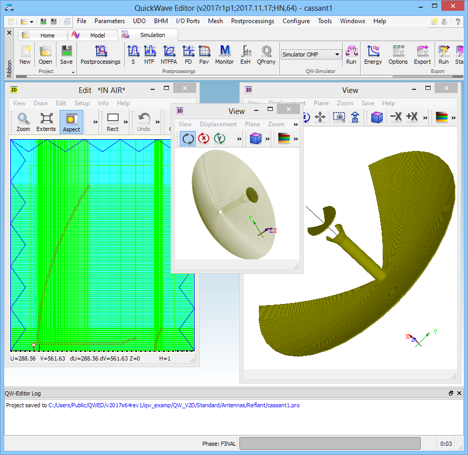
Two-reflector Cassegrain antenna (V2D BOR) project in QW-Editor.
This example presents a so called Cassegrain antenna wherein two reflectors are applied. The secondary reflector is a hyperbolic one (having its focal point behind the reflecting surface). The wave reflected from the secondary reflector impinges on the main parabolic reflector (having the focal point in front of the reflecting surface). Typically, the reflectors are placed in such a way that their focal points coincide.
The green box visible in the simulation model is NTF Box, which is a virtual box determining the boundaries at which the near-to-far field transformation will be executed for the purpose of calculating the radiation patterns.
In case of radiating scenarios, the entire project should be terminated with absorbing boundary conditions to model the free space surrounding. In this case we will use MUR absorbing boundary conditions in a form of MUR Box (blue box).
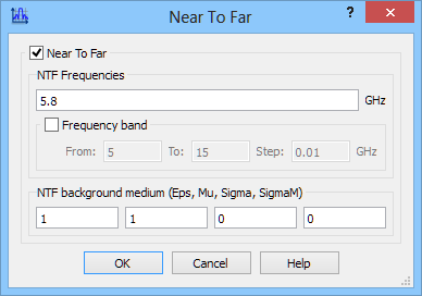
The radiation pattern calculation is activated with Near To Far postprocessing and is set at 5.8 GHz.
Near To Far postprocessing configuration dialogue.
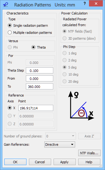
We wish to calculate the 2D radiation patterns versus angle Theta varying between 0 and 360 degrees with a step of 0.1 degrees. The definition of the angles is explained in the lower right part of the 2D Radiation Patterns configuration dialogue.
2D Radiation Patterns configuration dialogue.
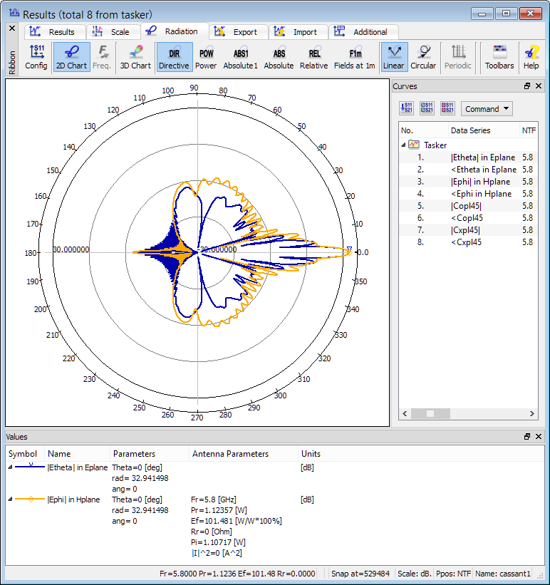
2D radiation patterns calculated at 5.8 GHz.
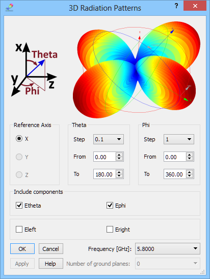
3D radiation pattern, with both Phi and Theta varying in steps, can be calculated in the 3D Radiation Pattern window. The 3D Radiation Patterns dialogue allows setting the reference axis and steps for angles Phi and Theta, defined with respect to that axis in the same way as for the 2D radiation pattern case. A single calculation frequency is also selected.
3D Radiation Patterns configuration dialogue.
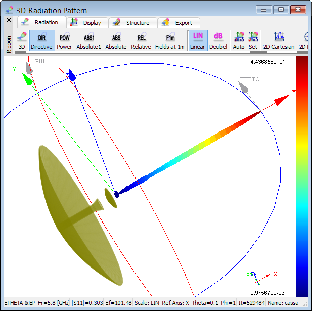
3D radiation pattern calculated at 5.8 GHz.
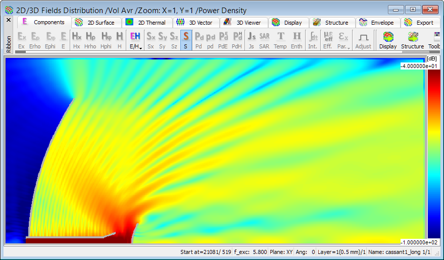
Distribution of time average envelope of the Poynting vector at 5.8 GHz.