Dielectric antenna (V2D BOR)
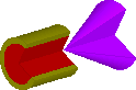
The present example considers an axisymmetrical circular dielectric antenna (V2D BOR).
Dielectric antenna (V2D BOR).
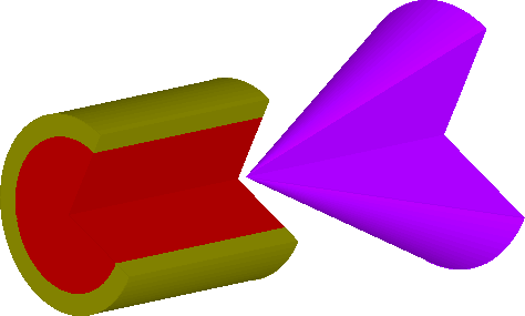
The structure is a dielectric antenna consisting of cylindrical waveguide filled with dielectric and dielectric cone at the opening of the waveguide.
Dielectric antenna (V2D BOR) - long section.
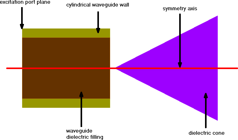
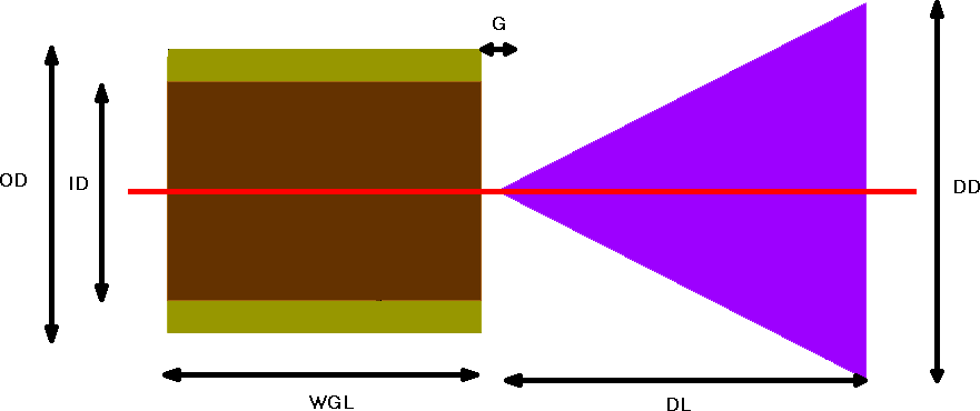
Dielectric antenna (V2D BOR) - dimmensions.
| Parameter |
OD |
ID |
WGL |
G |
DL |
DD |
| Value [mm] |
18 |
14 |
20 |
1 |
23.5 |
24 |
Dielectric antenna parameters.
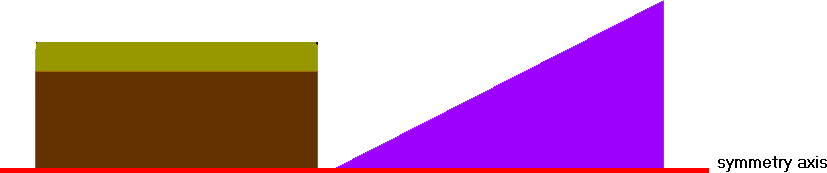
The structure that is analysed herein is an axisymmetrical dielectric antenna. Axial symmetry allows for performing the antenna analysis with ultra-fast vector 2D Bessel and FDTD hybrid solver (V2D BOR) designated for Bodies of Revolution (BOR) structures. This solver allows for analysing only half of structure's long-section, which results in its extremely fast performance. The structure should be drawn in a way that its symmetry axis coincides with project symmetry axis ρ=0 (in the QW-Editor and QW-Simulator referred as y=0).
Dielectric antenna (V2D BOR) - half of long section.
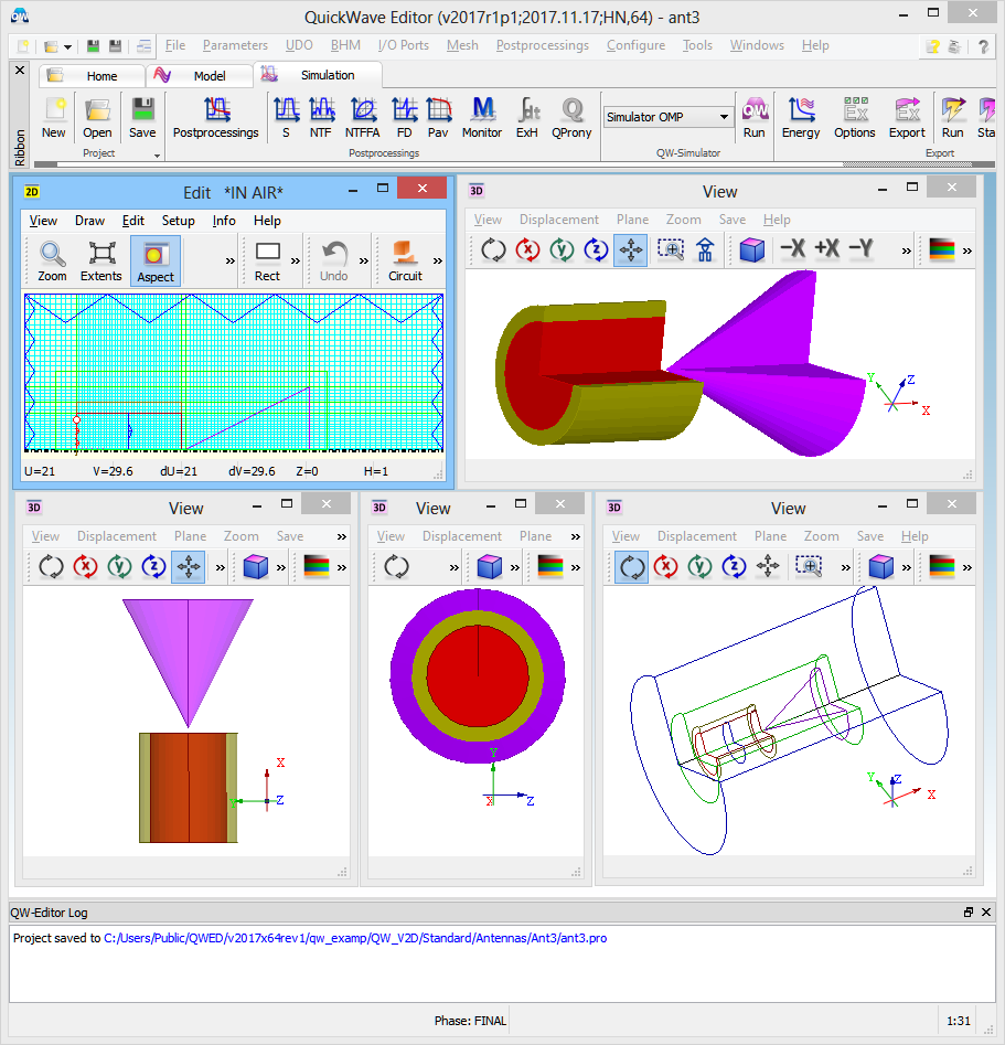
Dielectric antenna (V2D BOR) project in QW-Editor.
The dielectric materials used in the antenna are characterised by the following parameters:
- waveguide filling: εr= 3.6, µr= 1, σ=0, σM=0
- dielectric cone: εr= 2.1, µr= 1, σ=0, σM=0
The green box visible in the simulation model is NTF Box, which is a virtual box determining the boundaries at which the near-to-far field transformation will be executed for the purpose of calculating the radiation patterns.
In case of radiating scenarios, the entire project should be terminated with absorbing boundary conditions to model the free space surrounding. In this case we will use MUR absorbing boundary conditions in a form of MUR Box (blue box).
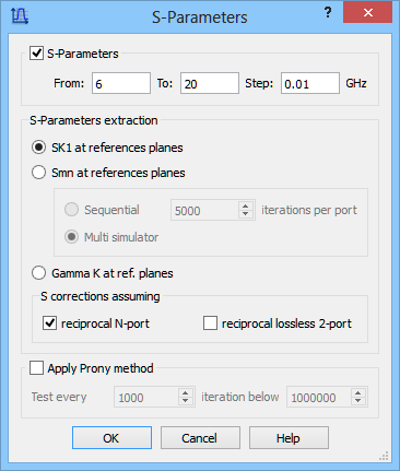
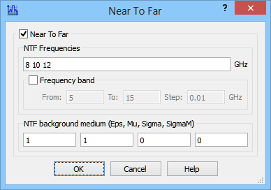
The antenna is fed by fundamental TE11 circular waveguide mode and is to be analysed in the frequency range from 6 to 20 GHz.
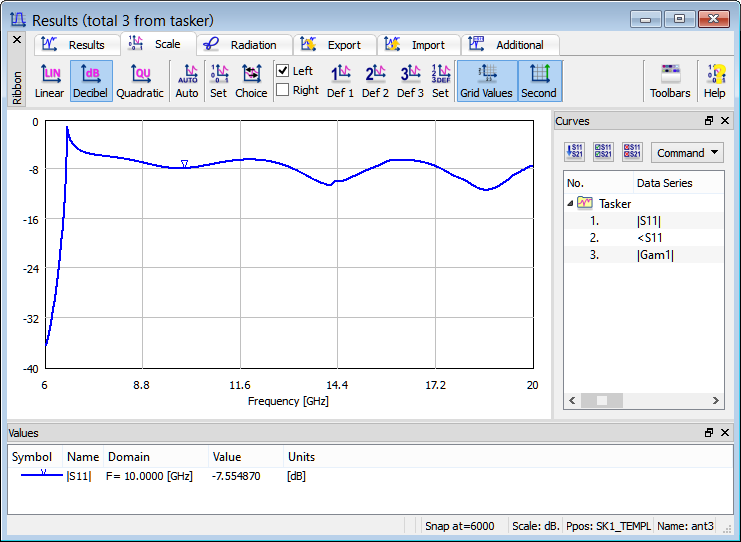
We are interested in obtaining reflection coefficient (S11) characteristic and the S-Parameters postprocessing is set from 6 GHz to 20 GHz with the frequency step of 0.01 GHz.
The radiation pattern calculations are set at 8 GHz, 10 GHz, and 12 GHz.
S-Parameters postprocessing and Near To Far postprocessing configuration dialogues.
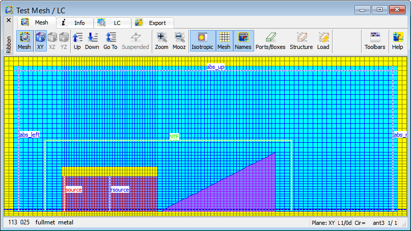
Effective FDTD mesh display - only one layer of a half of structure’s long-section.
Reflection coefficient of the considered dielectric antenna.
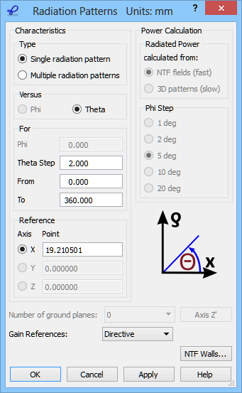
We wish to calculate the 2D radiation patterns versus angle Theta varying between 0 and 360 degrees with a step of 2 degrees. The definition of the angles is explained in the lower right part of the 2D Radiation Patterns configuration dialogue.
2D Radiation Patterns configuration dialogue.
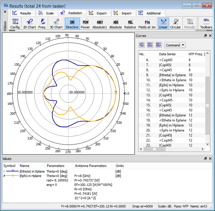
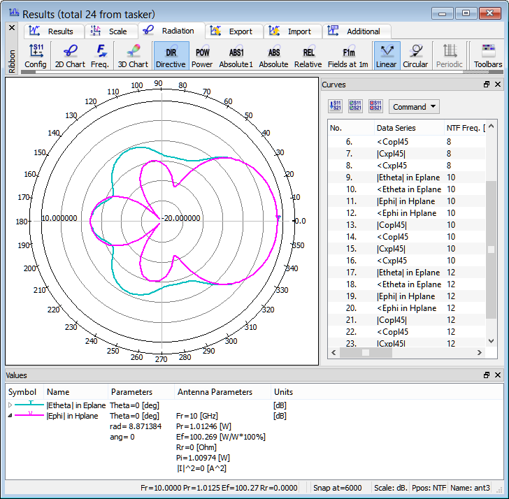
2D radiation patterns calculated at 8 GHz.
2D radiation patterns calculated at 10 GHz.
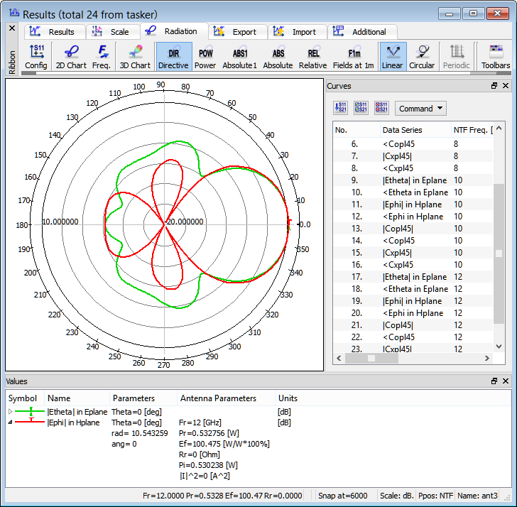
2D radiation patterns calculated at 12 GHz.
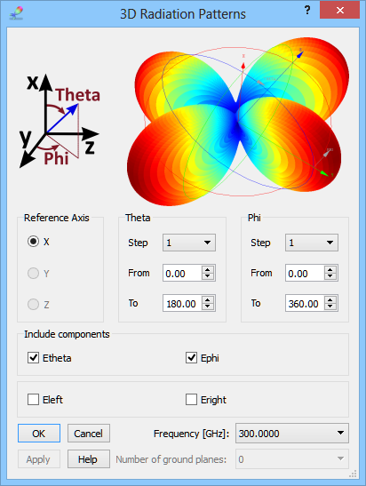
3D radiation pattern, with both Phi and Theta varying in steps, can be calculated in the 3D Radiation Pattern window. The 3D Radiation Patterns dialogue allows setting the reference axis and steps for angles Phi and Theta, defined with respect to that axis in the same way as for the 2D radiation pattern case. A single calculation frequency is also selected.
3D Radiation Patterns configuration dialogue.
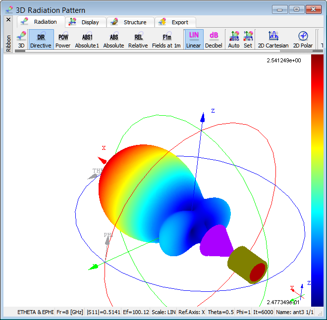
3D radiation pattern calculated at 8 GHz.
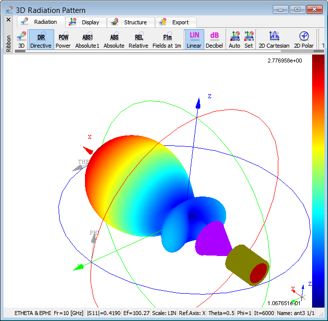
3D radiation pattern calculated at 10 GHz.
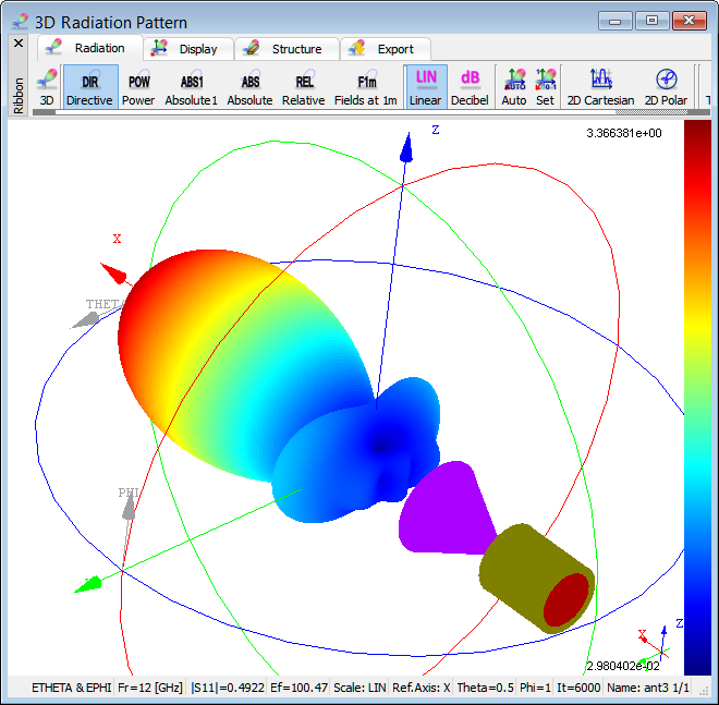
3D radiation pattern calculated at 12 GHz.
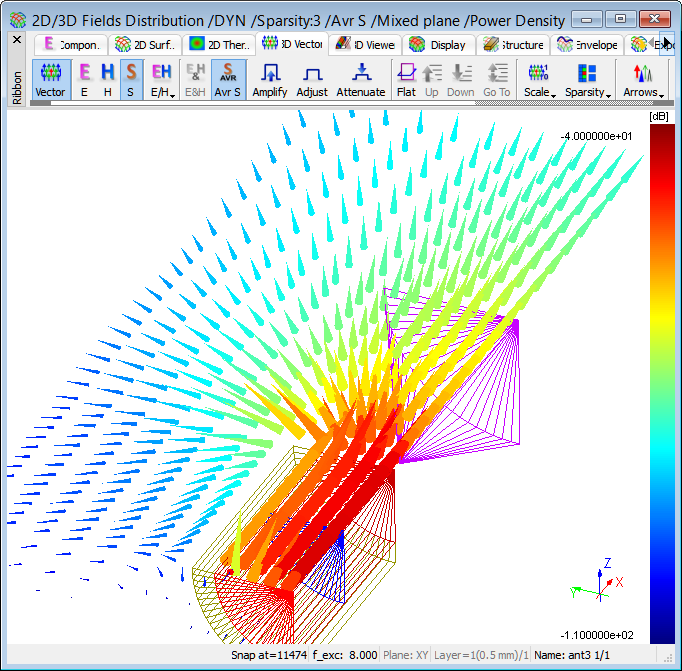
Distribution of Poynting vector at 8 GHz.