2.1.1 Settings panel
Settings panel contains buttons for dialogues with basic project settings (Circuit button) and for the Basic Heating Module.
Fig.A 2.1.1-1 Buttons in Settings panel.
![]() button opens the Circuit Settings dialogue containing basic project settings.
button opens the Circuit Settings dialogue containing basic project settings.
Frequency Range defines default frequency range used for postprocessings (Fig.A 2.1.4.1-1) and excitation waveform in ports (Fig.A 2.1.2.1-2, Fig.A 2.1.2.3-2 and Fig.A 2.1.2.5-2).
Geometry resolution defines the accuracy of project geometry.
Default Medium defines the medium of empty spaces inside the project boundaries (Fig.A 2.1.1.1-1). Regardless of the choice the external boundaries of the project are assumed to be made of Metal. Default Medium can be one of two available types, Air or Metal. Their parameters can be changed through Media Library if needed. Default Medium is shown in bold letters in the browser to help user distinguish it from other media.
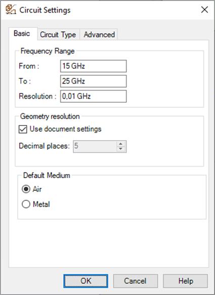
Fig.A 2.1.1.1-1 Basic settings in Circuit Settings dialogue.
Regardless of the choice of the default medium the default external boundaries of the FDTD mesh are assumed to be made of perfect electric conductor. To assign to them different properties we must do so explicitly by defining them as Absorbing Wall/Box (Fig.A 2.1.2.6-1, Fig.A 2.1.2.6-2 and Fig.A 2.1.2.7-1) or as special mesh borders (Fig.A 2.1.3.2-1 and Fig.A 2.1.3.2-2).
Circuit Type tab allows determining the type of the considered circuit and specific parameters assigned to the type. For typical three-dimensional problems 3D type is chosen. When analysing three-dimensional periodic structures the user should choose 3DP circuit. The Phase shift per period can be set explicitly or by defining the incidence angles of the illuminating wave (Angles of incidence). Axisymmetrical structures can be computed much faster when defined as 2DVcoa type. The structure is defined in XY plane with the symmetry axis placed at Y=0. Only the projects fulfilling the above are exported to QW-Simulator, others will be discarded. For axisymmetrical projects a proper Angular Variation needs to be defined.
2DV is usable for guided problems with a known phase constant. It is drawn as two dimensional structure on the XY Plane.
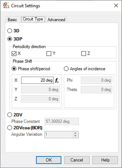
Fig.A 2.1.1.1-2 Circuit Type settings in Circuit Settings dialogue.
In Advanced tab we can find Metal Losses Bandwidth choices, which regards the bandwidth for rigorous consideration of frequency-dependent skin effect in lossy metals. It has to be pointed out that although the description of losses in metals by finite conductivity is essentially the same as that of lossy dielectrics, the level of conductivity makes a very significant difference. Due to very high conductivity the wavelength becomes so short that it is practically impossible to mesh the lossy metal volume. Thus instead, in QW-3D we virtually attach lossy elements to the magnetic field components tangential to the metal surface. To reproduce the frequency dependence, we attach to each of the tangential magnetic field components an RL ladder composed of a finite number (K) of cells. With the number K increasing we can model accurately the skin effect in a wider band, but at the price of increasing computer time and memory. That is why we allow the user to make a choice of the model to be used. The three options: Narrow, Decade and Two Decades correspond to the number K varying from 2 to 12, with appropriate change in wide band properties of the model. The central frequency for the band is taken as: in the case of sinusoidal excitation - frequency of the source; in the case of pulse excitation - central frequency of the band of postprocessing; in the case of pulse excitation and no postprocessing - 10 GHz.
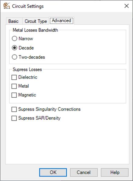
Fig.A 2.1.1.1-3 Advanced settings in Circuit Settings dialogue.
We also have five suppress options, for suppressing dielectric, metal or magnetic losses, singularity corrections, and SAR analysis. Suppressing the losses saves memory and computing time. Thus it is very convenient when we want to obtain faster preliminary simulation results without laborious modification of the entire project. Suppressing singularity corrections is only used in specific software operation, evaluating the influence of field singularities on the accuracy of FDTD results.
2.1.1.2 Basic Heating Module settings
 button opens the Basic Heating Module Settings dialogue with the settings available for QW-BHM module.
Allow BHM is an option available for QW-3D users who have the QW‑BHM licence. It instructs QW-Simulator to reserve more memory needed for QW‑BHM operations and sets several BHM parameters. If this option is enabled, then rotation movements can be added to the project (see Section A 2.2.2).
Allow Heat Flow checked causes that heat transfer analysis will be performed at each BHM step, if a proper Heat Flow module is set in Set Tools of QW-Simulator, and if all thermal media parameters are defined in media *.pmo files. For more details please refer to Chapter BHM 4.
The Tasker Times frame allows setting parameters for microwave heating process and is described in details in the QW-BHM manual.
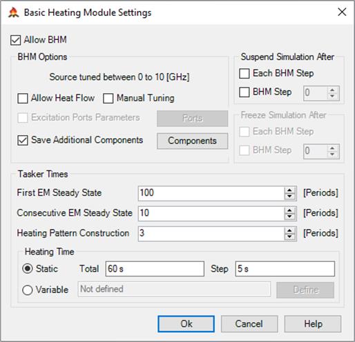
Fig.A 2.1.1.2-1 Basic Heating Module Settings dialogue.
Save additional components – when checked causes that the additional components will be saved by QW-Simulator after each BHM step. Additional components can be set in the Components dialogue available after clicking Components button. By default, the temperature patterns after consecutive BHM steps are saved in files. For convenience user can set up automatic suspend or freeze after each/particular BHM step.