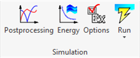
2.1.4 Simulation panel
Simulation panel contains commands and options related to the goals of simulation and its execution. In order to run the simulation, QW-AddIn needs to create the QW‑Simulator input. First step is the export to UDO file, which can be interpreted by QW-Editor. Then QW‑Editor generates proper FDTD mesh and exports QW‑Simulator project file. Simulation is ready to start.
Fig.A 2.1.4-1 Buttons inSimulation panel.
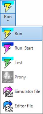
Fig.A 2.1.4-2 Drop-down button for running simulation.
![]() button opens the Postprocessing dialogue. In this dialogue user can enable required postprocessings and configure their options.
button opens the Postprocessing dialogue. In this dialogue user can enable required postprocessings and configure their options.
All postprocessings are listed in the Basic tab:
o FD‑probing
o FD‑Pavailable
o [S]‑differential
o NearToFar
o NTF Fix.Ang.
o FD‑Monitors
o ExH time integral
o Prony method
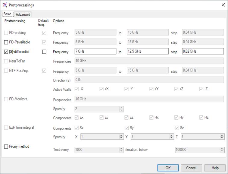
Fig.A 2.1.4.1-1 Basic tab of the Postprocessing dialogue.
The particular postprocessing can be enabled by checking the check box next to its name. Some of the postprocessings have also the check boxes in the Default freq. column. Checking this box tells QW‑AddIn to use the frequency range given in Circuit Settings dialogue (Fig.A 2.1.1.1-1) instead of the range given in Options column.
Detailed description of each postprocessing and its options can be found in QW‑Editor manual Section E 2.5.2.
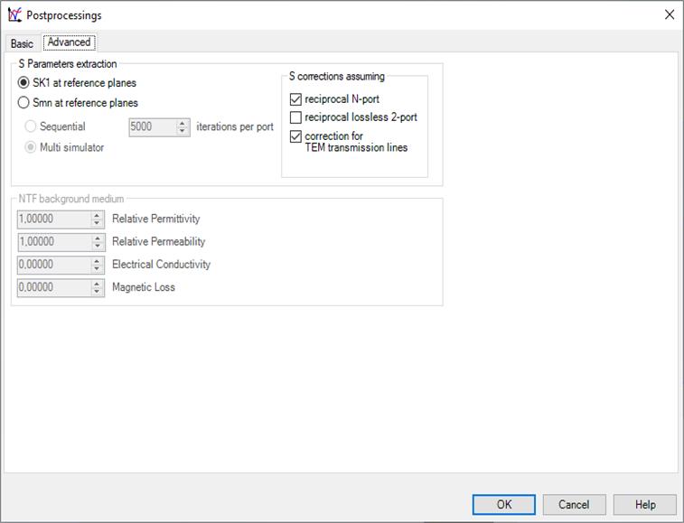
Fig.A 2.1.4.1-2 Advanced tab of the Postprocessing dialogue.
![]() button opens the Energy Stop Criterion dialogue allowing specifying the condition after with the simulation would automaticity stop. Detailed informations can be found in QW‑Editor manual .
button opens the Energy Stop Criterion dialogue allowing specifying the condition after with the simulation would automaticity stop. Detailed informations can be found in QW‑Editor manual .
Fig.A 2.1.4.2-1 Energy Stop Criterion dialogue.
![]() button opens the Export options dialogue allowing configuring various factors associated with project export. The most important is QuickWave Software tab where user can select which version of QuickWave software will be used for calculations. QW-Simulator type combo box allows choosing which type of QW-Simulator will be used for simulation. Mostly used types are "OMP" - solution for multiprocessor/multicore platforms and "GPU" – solution for graphics card of massively parallel architecture. Refer to other manuals for further information.
button opens the Export options dialogue allowing configuring various factors associated with project export. The most important is QuickWave Software tab where user can select which version of QuickWave software will be used for calculations. QW-Simulator type combo box allows choosing which type of QW-Simulator will be used for simulation. Mostly used types are "OMP" - solution for multiprocessor/multicore platforms and "GPU" – solution for graphics card of massively parallel architecture. Refer to other manuals for further information.
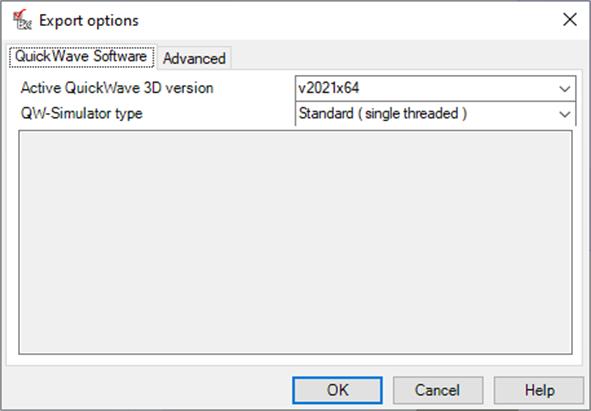
Fig.A 2.1.4.3-1 QuickWave Software tab of the Export options dialogue.
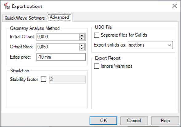
Fig.A 2.1.4.3-2 Advanced tab of the Export options dialogue.
Advanced tab contains various geometry analysis and UDO file creation options.
UDO File – configures UDO file creation process. If Separate files for Solids option is checked, a separate UDO file for each Solid will be created while exporting the project. Export solids as allows user to select how Solids will be exported to QuickWave: as sections or as elements. Sections is a default and recommended option.
Export Report – if Ignore Warnings option is enabled, the export report dialogue will not be displayed during the project export, unless some serious problems occur.
Geometry Analysis Method – defines the parameters used by geometry analysis algorithm. Those options were introduced for some very special applications and are not recommended for a general use.
Simulation – Stability factor is advanced setting allowing to control numerical stability of the algorithm (precisely it describes relation between cell size and time step). Detailed information can be found in simulator’s help (QuickWave 7.3).
![]() exports UDO file, runs silently QW‑Editor, creates project file and runs QW‑Simulator.
exports UDO file, runs silently QW‑Editor, creates project file and runs QW‑Simulator.
![]() exports UDO file, runs silently QW‑Editor, creates project file, runs QW‑Simulator and starts the simulation automatically.
exports UDO file, runs silently QW‑Editor, creates project file, runs QW‑Simulator and starts the simulation automatically.
![]() exports UDO file, runs silently QW‑Editor, creates project file, runs QW‑Simulator and opens Test Mesh window (see Section S 2.6 in QW‑Simulator manual).
exports UDO file, runs silently QW‑Editor, creates project file, runs QW‑Simulator and opens Test Mesh window (see Section S 2.6 in QW‑Simulator manual).
![]() exports UDO file, runs silently QW‑Editor, creates project file, runs QW‑Simulator and starts QProny module. For more information please refer to QProny manual.
exports UDO file, runs silently QW‑Editor, creates project file, runs QW‑Simulator and starts QProny module. For more information please refer to QProny manual.
![]() exports UDO file, silently runs QW‑Editor and then creates project file.
exports UDO file, silently runs QW‑Editor and then creates project file.
![]() exports UDO file and opens it in QW-Editor.
exports UDO file and opens it in QW-Editor.