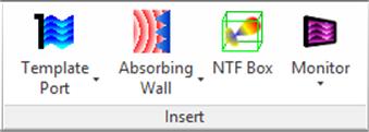
2.1.2 Insert panel
Insert panel contains buttons for adding ports, boundaries, Near To Far and Monitor boxes.
Fig.A 2.1.2-1 Buttons inInsert panel.
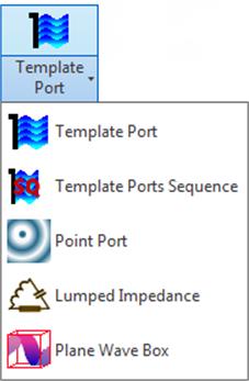
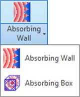
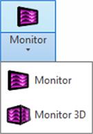
Fig.A 2.1.2-2 Drop-down buttons for ports, boundaries and Monitors.
![]() button opens the Add Template Port dialogue.
button opens the Add Template Port dialogue.
The first step is setting up the geometry. It is done by choosing the port's anchor. Port's dimensions and location will be based on this object and changing it will change the port as well. The object can be either Edge Loop or Sketch profile parallel to the XY, YZ, or XZ plane. Port anchor can be re‑selected at any time by pressing ![]() (this operation resets the port geometry). When the port anchor is selected, the port will be shown on the model view.
(this operation resets the port geometry). When the port anchor is selected, the port will be shown on the model view.
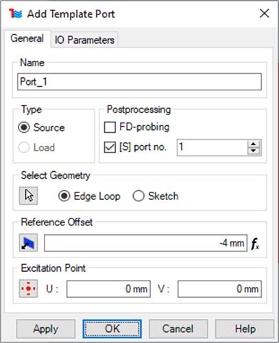
Fig.A 2.1.2.1-1 Add Template Port dialogue.
In the General tab of the Edit Template Port dialogue the user can configure the following port properties:
· Name – name used to identify the port. This name will be also used in QW-Editor project file.
· Type – indicates if the port is a source or an output port.
· Postprocessing – indicates what postprocessings are available for that port. The [S] port no. equal 1 is reserved only for “source” type port. All the ports (both Point Ports and Template Ports) should have unique number and they should be numbered in order starting from 1.
· Reference offset – by default distance between port and reference is equal maximum cell sizes (in each direction) multiplied by three. The reference plane can be moved by using ![]() button or by changing the value of the field next to that button. Changing directly the value in the text box creates Inventor's parameter associated with Reference offset allowing user to control it externally through Parameters dialogue. In this case
button or by changing the value of the field next to that button. Changing directly the value in the text box creates Inventor's parameter associated with Reference offset allowing user to control it externally through Parameters dialogue. In this case ![]() marker will be shown on the right side of the text box (see Fig.A 2.1.2.1-1 for example).
marker will be shown on the right side of the text box (see Fig.A 2.1.2.1-1 for example).
· Excitation point – excitation point location can be changed within the Template Port rectangle. Position can be edited using a mouse, floating dialogue after pressing ![]() or by changing the values of the “U” and “V” fields. Similarly as for the Reference offset these values can be made the Inventor's parameters.
or by changing the values of the “U” and “V” fields. Similarly as for the Reference offset these values can be made the Inventor's parameters.
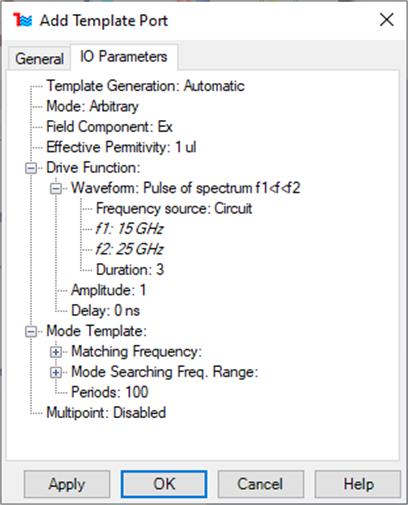
Fig.A 2.1.2.1-2 IO Parameters tab in theAdd Template Port dialogue.
The port excitation can be configured in the I/O Parameters tab. Description of all the fields available in this dialogue can be found in QW-Editor manual Section E 2.5.1. Waveform frequencies as default are taken automatically from Circuit Settingsdialogue. To set them manually change Frequency Sourcefrom Circuit to Manual. The port configuration is confirmed by pressing the OK button. New port will be added to the project. All ports available in the project are listed in the QW Model tree browser in the Ports node. All ports are also visible in the model view window.
2.1.2.2 Template Ports Sequence
![]() button opens Add Sequenced Template Ports dialogue. Multiple ports could be created here quickly, each having different mode. Modes are ordered in sequence from the lowest possible up to either maximum possible or specified by the user. Geometry and IO Parameters are shared between created ports.
button opens Add Sequenced Template Ports dialogue. Multiple ports could be created here quickly, each having different mode. Modes are ordered in sequence from the lowest possible up to either maximum possible or specified by the user. Geometry and IO Parameters are shared between created ports.
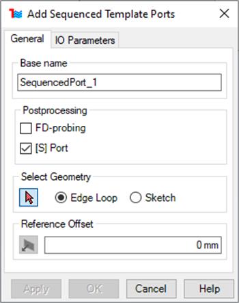
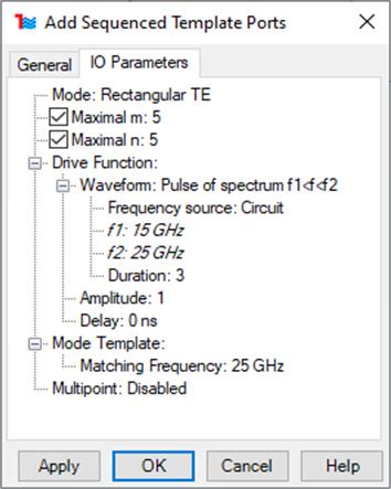
Fig.A 2.1.2.2-1 General and IO Parameters tab in the Add Template Port dialogue.
Most configurations are similar to these found in singular Template Port. Ports will have names consisting of user defined base name and automatically generated postfix denoting mode. For each port [S] port no. would be lowest available.
![]() button opens the Add Point Port dialogue.Point Port describes a lumped port defined by its current and voltage at certain nodes. An equivalent circuit model of the port consists of a voltage source in series with a resistor, or equivalently, a current source in parallel with a resistor.
button opens the Add Point Port dialogue.Point Port describes a lumped port defined by its current and voltage at certain nodes. An equivalent circuit model of the port consists of a voltage source in series with a resistor, or equivalently, a current source in parallel with a resistor.
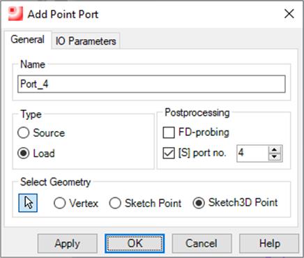
Fig.A 2.1.2.3-1 Add Point Port dialogue.
To create point port either Vertex, Sketch Point or Sketch Point 3D must be set as anchor point. Port anchor can be re-selected at any time by pressing ![]() (this operation resets the port geometry). When the port anchor is selected, port will be shown on the model view.
(this operation resets the port geometry). When the port anchor is selected, port will be shown on the model view.
Point Port will serve as a source or a probe depending whether Source or Load is checked. It is possible to perform the S-matrix calculations for a Point Port. In this case number is associated with the port ([S] port no.). All the ports (both Point Ports and Template Ports) should have a unique number and they should be numbered in order starting from 1 reserved for a source. Point Ports can also serve as points for FD-probing postprocessing (Fig.A 2.1.4.1-1).
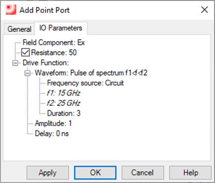
Fig.A 2.1.2.3-2 IO Parameters tab in theAdd Point Port dialogue.
IO Parameters have been described in details in Section E 2.5.1 of the QW-Editor manual. Polarisation defines a field component to which the port is connected. Resistance can be set as self-adjusted by unchecking check box next to the label. Setting Resistance to ∞ can be achieved by typing „infinity” or „INF” instead of a number.Waveform frequencies as default are taken automatically from Circuit Settingsdialogue. To set them manually change Frequency Sourcefrom Circuit to Manual.
![]() button opens the Add Lumped Impedance dialogue.Lumped Impedance describes a lumped circuit with specified parameters.
button opens the Add Lumped Impedance dialogue.Lumped Impedance describes a lumped circuit with specified parameters.
To create lumped impedance either Vertex, Sketch Point or Sketch Point 3D must be set as anchor point. Lumped impedance anchor can be re-selected at any time by pressing ![]() (this operation resets the port geometry). When the lumped impedance anchor is selected, lumped impedance will be shown on the model view.
(this operation resets the port geometry). When the lumped impedance anchor is selected, lumped impedance will be shown on the model view.
In the Parameters frame, the user can independently choose the parameters of the lumped circuit. Under the Type list five circuits are available: Series, Parallel, Drude, Debye, and Lorentz. The visualisation of the chosen circuit, indicating the particular p and s parameters available on the right, will appear on the picture. At the bottom of the Parameters frame the field Component to which the circuit is connected can be chosen.
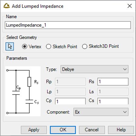
Fig.A 2.1.2.4-1 Add Lumped Impedance dialogue.
![]() button opens the Add PlaneWave Box dialogue. Plane Wave Boxes are auxiliary surfaces used for exciting an incident plane wave.
button opens the Add PlaneWave Box dialogue. Plane Wave Boxes are auxiliary surfaces used for exciting an incident plane wave.
Box geometry can be created using one of two methods:
· Project Geometry – specify offset between the box borders and project elements (Solids, Thin Layers and Wires)
· Custom Geometry – select two anchor objects (either Face or Sketch entity) defining bounds of the box. The size of Plane Wave Box is automatically adjusted after the anchors change. Anchor can be re-selected after pressing ![]() button.
button.
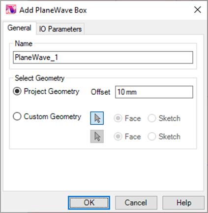
Fig.A 2.1.2.5-1 Add PlaneWave Box dialogue.
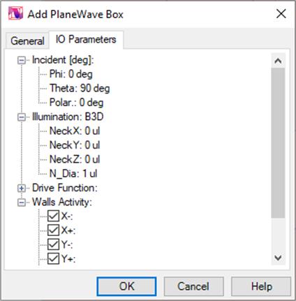
Fig.A 2.1.2.5-2 IO Parameters tab in theAdd PlaneWave Box dialogue.
Plane Wave Box is configured in IO Parameters tab of the dialogue. Detailed description of each parameter can be found in Section E 2.5.1.4. of the QW-Editor manual. Additionally the user can suppress activity of the walls of the Plane Wave Box in any directions by checking off sub‑nodes under Walls Activity (Fig.A 2.1.2.5-2). Waveform frequencies as default are taken automatically from Circuit Settingsdialogue. To set them manually change Frequency Sourcefrom Circuit to Manual.
Every created Plane Wave Box is added to the Ports node in the QW Model browser pane.
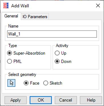
![]() button opens the Add Wall dialogue used for adding absorbing walls.
button opens the Add Wall dialogue used for adding absorbing walls.
Absorbing walls are used for absorbing termination of a chosen rectangular part of the FDTD mesh. It is not used for extracting any parameters for further postprocessing. Its geometry is based on the anchor – either Face or Sketch perpendicular to one of the basic planes. Anchor can be re-selected after pressing ![]() button.
button.
There are two types of absorbing walls. Boundary condition of Super‑Absorbing wall stands for Mur with superabsorbing. Boundary condition of PML wall stands for Perfectly Matched Layer. Wall type can be changed in Type group in General tab (Fig.A 2.1.2.6-1).
Fig.A 2.1.2.6-1 Add Wall dialogue.
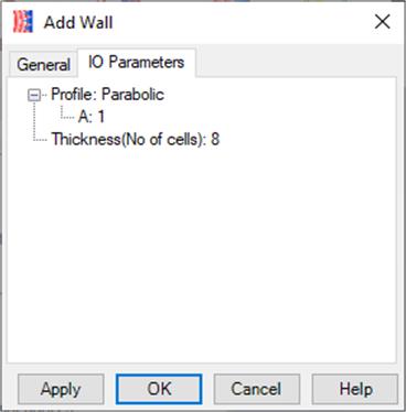
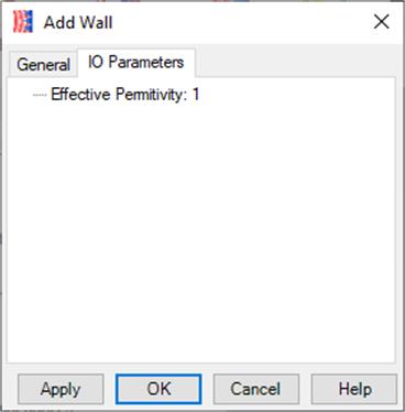
Fig.A 2.1.2.6-2 IO Parameters tab for PML and Super-Absorption wall type in the Add Wall dialogue.
Each wall is active only in the selected direction, orthogonal to the wall plane. If Activity is set to Up, the wall will absorb radiation coming from above the wall plane. If configured otherwise the wall will absorb radiation from below that plane.
Output parameters are configured in IO Parameters tab (Fig.A 2.1.2.6-2). Differences between PML and Super-Absorbing Walls are described in details in Section E 2.5.1.2. of the QW-Editor manual.
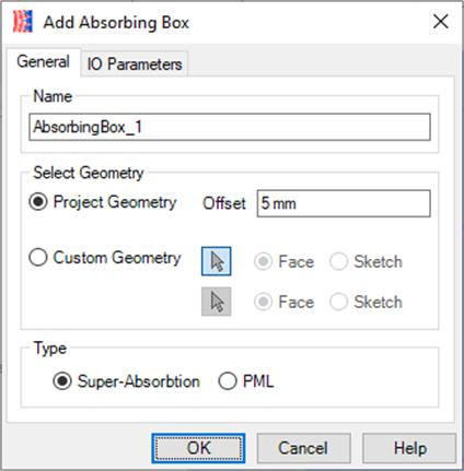
![]() button opens the Add Absorbing Box dialogue.
button opens the Add Absorbing Box dialogue.
Fig.A 2.1.2.7-1 Add Absorbing Box dialogue.
Box position and size can be defined by:
· Project Geometry – specify offset between the box borders and project elements (Solids, Thin Layers and Wires)
· Custom Geometry – select two anchor objects (either Face or Sketch entity) defining bounds of the box. The size of the box is automatically updated after the anchors change.
Dialogue used for the box configuration is similar to the Add/Edit Wall dialogue. Activity of each wall in the box is directed into the box. If a radiation source is located inside the box all its power will be absorbed by the box.
![]() button opens the Add Monitor dialogue used for adding monitors. Monitor allows observation of selected EM field components for specified frequencies on the marked surface.
button opens the Add Monitor dialogue used for adding monitors. Monitor allows observation of selected EM field components for specified frequencies on the marked surface.
Monitors define only the surfaces at which certain EM field are calculated. They do not have any influence on field distribution. Monitors do not have any parameters except of geometry which can be defined in one of two ways: by Face or Sketch profile. These need to be a single planar (2D) surface orthogonal to X, Y or Z axis. Anchor can be re-selected after pressing ![]() button.
button.
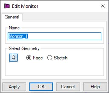
Fig.A 2.1.2.8-1 Add Monitor dialogue.
Frequencies and field components observed by all monitors are configured in the Postprocessing dialogue in FD-Monitors part. More detailed description of monitors can be found in Section E 2.5.2 of the QW-Editor manual.
![]() button opens the Add Monitor 3D dialogue.
button opens the Add Monitor 3D dialogue.
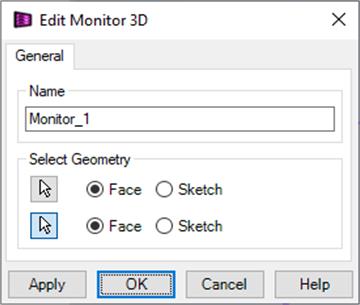
Fig.A 2.1.2.9-1 Add Monitor dialogue.
Monitor 3D is similar to simple Monitor but it is not limited to the 2D area. Monitors 3D allow observation of selected EM field components for given frequencies inside marked volume. More detailed description of monitors can be found in Section E 2.5.2 of the QW-Editor manual.
Monitor 3D geometry is defined by selecting two anchors either Faces or Sketch entities. Anchor can be re-selected after pressing ![]() button.
button.
 button opens the Add NTF Box dialogue.
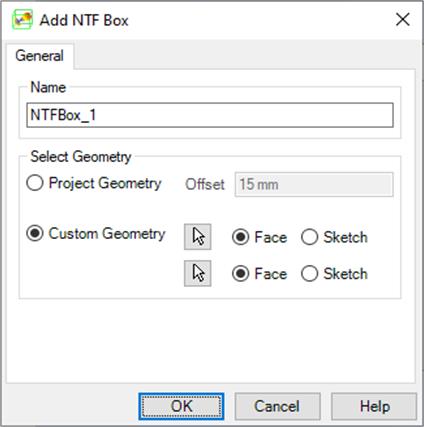
Fig.A 2.1.2.10-1 Add NTF Box dialogue.
Near-To-Far (NTF) transformation surfaces available in the project are listed in NTF node of the QW Model browser pane. NTF Box button opens a dialogue for configuration of the new NTF Box. Detailed description of the NTF Boxes can by found in Section E 2.2.3 of the QW-Editor manual.
The position and size of NTF Box can be defined by:
· Project Geometry – by specifying the offset between the box borders and project elements (Solids, Thin Layers and Wires)
· Custom Geometry – by selecting two anchor objects (either Face or Sketch entity) defining bounds of the box. The size of the box updates automatically when the anchors change. Anchor can be re-selected after pressing ![]() button.
button.
NTF boxes are a set of surfaces on which Near-To-Far transformation is calculated. It has no influence on the EM field distribution. All the NTF postprocessing parameters are configured in the Postprocessing dialogue (Fig.A 2.1.4.1-1).