2.2.2 Movements
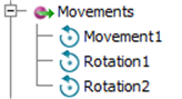
Fig.A 2.2.2-1 Movements browser node.
Movement object describes modifications of the element’s position performed during simulation. Basic Heating Module should be set as active (Fig.A 2.1.1.2-1) for Movements to be accessible. All defined movements are listed in the browser in the Movements node.
New movements can be added by selecting New movement command (hidden if Basic Heating Module is not active) from the context menu of either Movements node or any of previously defined movements (Fig.A 2.2.2-2). The Add Movement dialogue will be opened (Fig.A 2.2.2-3). Current version of the QW-AddIn supports only rotation and trajectory in xy-plane movements.
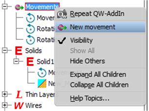
Fig.A 2.2.2-2 Movement's context menu.
Rotation Movement can rotate solids only in XY plane along axis parallel to Z axis. Creating proper axis can be done by selecting edge or solid body from the project (Fig.A 2.2.2-2). It will contain the middle point of selected object. User can define offset of the rotation axis from this point using X and Y coordinates text boxes. Movement’s location can be changed by clicking ![]() button. Rotation Speed parameter describes number of full rotations per minute.
button. Rotation Speed parameter describes number of full rotations per minute.

Fig.A 2.2.2-3 Add Movement dialogue with Rotation movement type and visible rotation axis.
Trajectory XY Movement can only define movement in XY plane. Trajectory first point always is origin point (0,0). User add coordinates of subsequent points. In the example square shape for trajectory is shown (Fig.A 2.2.2-4).
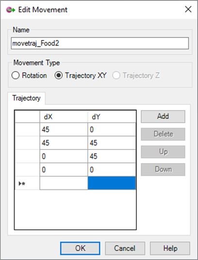
Fig.A 2.2.2-4 Trajectory XY movement type in the Edit Movement dialogue defining movement along square shape.
Movement should be associated to solid using Select Movement command from solids context menu in the QW Model tree (Fig.A 2.2-4). If Basic Heating Module is active, then associated Movement will be displayed under solid node.