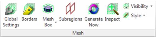
2.1.3 Mesh panel
Mesh panel contains buttons for setting, generating and inspecting FDTD mesh. Similarly to QW‑Editor, the visualisation of the mesh can be enabled or disabled according to user’s preferences.
Fig.A 2.1.3-1 Buttons inMesh panel.
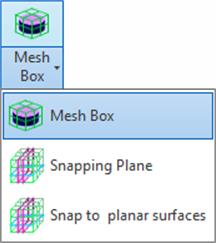
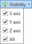
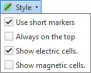
Fig.A 2.1.3-2 Drop-down button for mesh controls and options for mesh visualisation.
![]() opens Mesh settings dialogue where mesh generation parameters can be configured.
opens Mesh settings dialogue where mesh generation parameters can be configured.
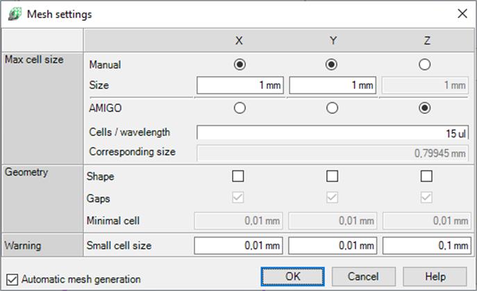
Fig.A 2.1.3.1-1 Mesh Settings dialogue.
Most of the mesh generation options are set for each axis separately. The options are grouped into three categories:
· Max cell size – global maximum cell size policy.
· Geometry – automatic mesh adjustment to the circuit geometry.
· Warning – defines a maximum cell size that is not qualified and highlighted as a small cell.
Max cell size stands for the maximum mesh cell size allowed to be generated in the circuit. User can chose between two different methods of defining maximum cell size:
· Manual – maximum cell size is a fixed value given by the user. To enable this policy for any axis check the radio button in Manual row and put the value of the upper size limit in text box in Size row.
· By Wavelength – maximum cell size is defined through number of cells per wavelength (at the highest specified frequency) ratio. The wavelength is defined as a shortest wavelength that can occur in each medium present in the project, corresponding to the frequency range given in Circuit Setting dialogue (Fig.A 2.1.1.1-1). To enable this max cell size policy for a given axis check the radio button in the By Wavelength row. Number of cells per wavelength is configured for all axes at once in Cells / wavelength row. Corresponding size is the smallest cell size generated with this method.
The above described settings can be locally changed with Mesh Boxes (Fig.A 2.1.3.3-1) and Snapping Planes (Advanced tab, Fig.A 2.1.3.4-1). Mesh Boxes can only increase mesh density and Snapping Planes are able to locally override maximal cell size.
In Geometry group user can configure the following options:
· Shape – if checked automatic mesh adjustment to the shape of existing elements is performed. QW‑AddIn will analyse the project's geometry and place FDTD cells borders to improve shape approximation.
· Gaps – in this option the mesh generation mechanism is additionally analysing the distance between elements’ faces. This option improves the approximation of gaps in single element, gaps between different elements, and also areas where geometry is very thin, like metal sheets.
· Minimal cell – is a smallest cell size allowed to be generated by geometry analysis algorithm. Smaller value allows better geometry approximation but increases the overall number of generated FDTD cells. This option is active only, if Shape option is enabled.
Note that in case of very complex circuits geometry adjustment options should be enabled with caution as they can be very time consuming.
Small cell size option in Warning group, allows user to specify the smallest cell size that is considered acceptable. All cells with a smaller size will be highlighted in Inspect Mesh dialogue and also shown on mesh graphics when visible (Fig.A 2.1.3.9-1) .
Automatic mesh generation enforces automatic mesh (re)generation after each project geometry modification. For large-scale projects mesh generation can be time consuming so it might be more convenient to turn this option off. To minimise to amount of automatic regenerations Mesh is only generated when needed (e.g. for export, Inspect Mesh dialogue). Therefore user can notice during normal work that Generate Now ribbon button is highlighted (indicating mesh not being valid) even when Automatic mesh generation is enabled – in that case software is just waiting for first operation that will request mesh data.
![]() button opens Mesh borders dialogue.
button opens Mesh borders dialogue.
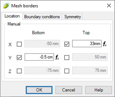
Fig.A 2.1.3.2-1 Location and Boundary conditions tabs of Mesh borders dialogue.
By default, mesh is automatically expanded to include all objects in the model. User can manually adjust individual project boundaries in Location tab of Mesh borders dialogue. All objects/geometries placed outside of the box defined by the chosen coordinates will be ignored while exporting the project to QW-Simulator.
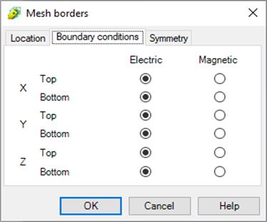
In Boundary conditions tab (Fig.A 2.1.3.2-1), the boundary condition for each mesh border can be set to Electrical (default) or Magnetic.
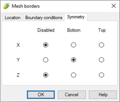
Fig.A 2.1.3.2-2 Symmetry tab of Mesh borders dialogue.
Additionally, each of the project boundaries can be set to be a symmetry plane, if applicable in the project. This choice is made through the Symmetry tab (Fig.A 2.1.3.2-2). This will result in smaller project exported to simulator, therefore faster computation.
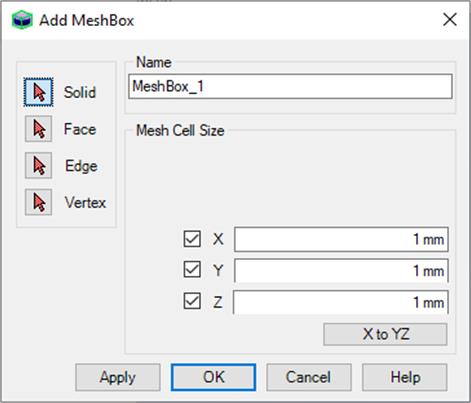
![]() button opens a dialogue for adding new Mesh Box.
button opens a dialogue for adding new Mesh Box.
Mesh Box is a simple object for meshing configuration in the selected area. User can specify the maximum cell size allowed inside the box. Different values can be given for each axis. It is also possible to disable mesh modification along each axis separately. Mesh Box geometry is always based on existing part objects. User can select elements that must be contained inside the box. If the geometry of those objects is changed the box will automatically update its size.
Fig.A 2.1.3.3-1 Add MeshBox dialogue.
Mesh box ensures that all elements included inside the box will be analysed with the accuracy not worse than the one corresponding to the given FDTD cell size. If the mesh boxes overlap on each other, the smallest cell size from the defined ones is used in this area. Mesh snapping planes can override the maximal cell size given by the mesh boxes. Mesh Boxes are recommended as a cell size configuration utility.
Mesh Box can be anchored to multiple Solids, Faces, Edges or Vertexes. One Mesh Box can be based on many objects of different types.
![]() button opens the Add Snapping Plane dialogue.
button opens the Add Snapping Plane dialogue.
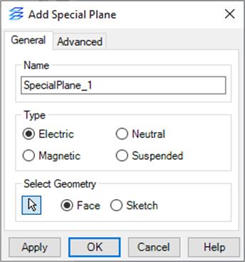
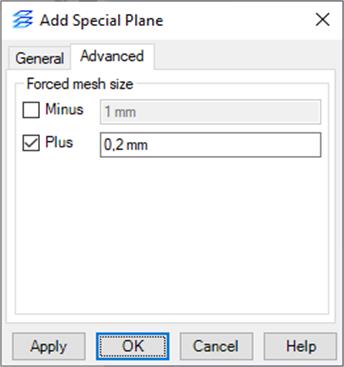
Special Plane requires specifying anchor as Face or Sketch profile. Face and Sketch have to be parallel to the XY, YZ, or XZ plane. Special Plane anchor can be re‑selected at any time after pressing ![]() button. The General tab of the Edit Mesh Snapping Plane dialogue (Fig.A 2.1.3.4-1) allows the user to set custom name and select the type of the special plane. Types of the special planes are described in the QW-Editor manual. In the Advanced tab user can set sizes of the mesh cells above and below the added special plane. It is recommended to use Snapping planes mainly for snapping the mesh lines to the objects. For configuring the cells size the Mesh Boxes is recommended.
button. The General tab of the Edit Mesh Snapping Plane dialogue (Fig.A 2.1.3.4-1) allows the user to set custom name and select the type of the special plane. Types of the special planes are described in the QW-Editor manual. In the Advanced tab user can set sizes of the mesh cells above and below the added special plane. It is recommended to use Snapping planes mainly for snapping the mesh lines to the objects. For configuring the cells size the Mesh Boxes is recommended.
Fig.A 2.1.3.4-1 General and Advanced tabs in theAdd Special Plane dialogue.
2.1.3.5 Snap to planar surfaces
![]() opens the Add special planes at planar surfaces dialogue.
opens the Add special planes at planar surfaces dialogue.
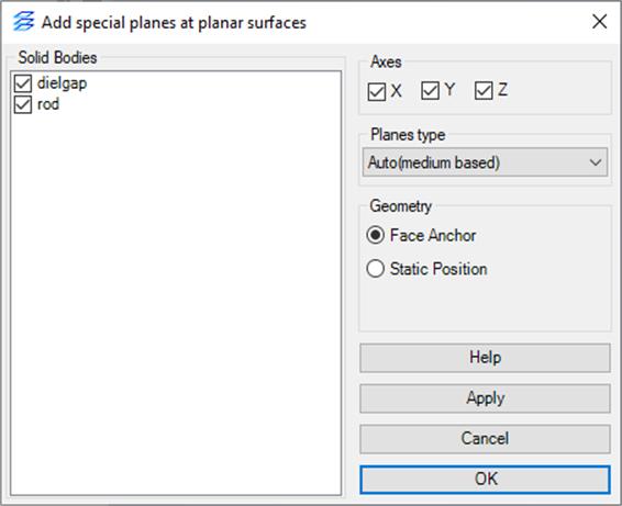
Fig.A 2.1.3.5-1 Add special planes at planar surfaces dialogue.
It is a tool for adding multiple snapping planes at each planar face surfaces of the selected solid bodies. User can choose solids, axes and snapping plane type. Once the choice is confirmed with OK button new special planes will be added at each planar face, (orthogonal to one of the selected axes) of selected solids.
As default new snapping planes are added with Face Anchor (similarly to those created by the user in Add Snapping Plane dialogue). With large amount of objects this process can take heavy toll on performance. In that case it is advised to use Static Position in Geometry option. New snapping plane location will be fixed and will not react to parameters manipulation. They will not be added if another snapping plane is already located at the face position (even if the existing plane is not exported to UDO).
![]() forces mesh (re)generation. When this button is not greyed-out then current mesh is in invalid state and it requires update. Mesh is not updated automatically (unless Automatic mesh generation option is checked in the Mesh Settings dialogue, see Fig.A 2.1.3.1-1) after each project geometry modification and for large-scale projects mesh generation can be time consuming. Thus, it is important to generate mesh before running simulation.
forces mesh (re)generation. When this button is not greyed-out then current mesh is in invalid state and it requires update. Mesh is not updated automatically (unless Automatic mesh generation option is checked in the Mesh Settings dialogue, see Fig.A 2.1.3.1-1) after each project geometry modification and for large-scale projects mesh generation can be time consuming. Thus, it is important to generate mesh before running simulation.
 opens Create Subregions dialogue.
In QW-Simulator MultiGPU, the user establishes how many devices will be used for particular project calculation. The decision is made beforehand. Every device is running its own part of the project called Subregion. User can create them by adding a plane called Subregion Border. Project exported with Subregions can be simulated only in QW-Simulator MultiGPU.
Subregion Borders are allowed along one direction only (X, Y or Z).
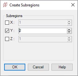
Fig.A 2.1.3.7-1 Create Subregions dialogue.
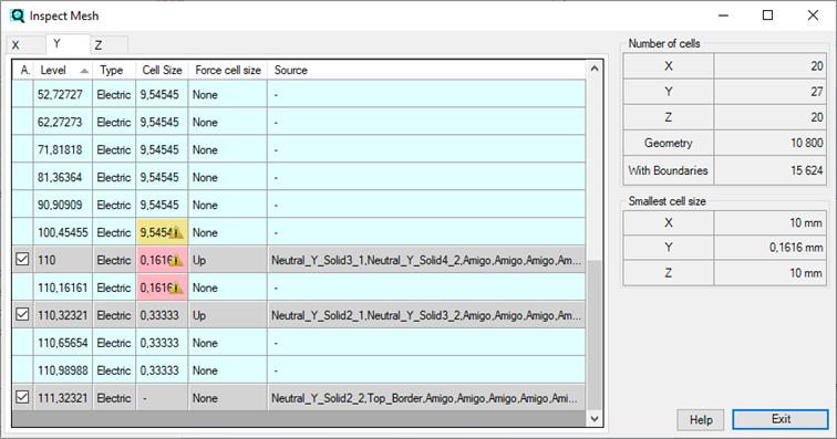
![]() button opens the Inspect dialogue that can be useful for controlling the mesh. The main part of the dialogue is a table with a list of all mesh half-cells borders (Fig.A 2.1.3.8-1). Each table row represents different half-cell border.
button opens the Inspect dialogue that can be useful for controlling the mesh. The main part of the dialogue is a table with a list of all mesh half-cells borders (Fig.A 2.1.3.8-1). Each table row represents different half-cell border.
The table contains the following columns:
· Active – the check box indicates if the Source which snaps the mesh half-cell border is exported to UDO file or is it disabled. Disabled Snapping Planes items are also listed in the table. Double‑clicking on the level with Snapping Plane switches that plane's activity. Levels created by other objects (grey row background) cannot be disabled in the dialogue.
· Level – the coordinate (see active tab name) at which mesh cell border is located. This value is given in the project's units.
Fig.A 2.1.3.8-1 Mesh cells borders table for Y coordinate in Inspect dialogue.
· Type – describes if the level is Electric (cell border) or Magnetic (middle of the mesh cell).
· Cell size – size of the FDTD cell above the given level. If this value is set to “-“ then there are no cells generated above them. Yellow and red backgrounds in this column symbolizes various warnings. Former displays that adjacent cells have big difference in their sizes (multitude of 10x and up) while latter show user defined Small Cell Size warning (see Mesh Settings for details). Hovering over warning icon shows description.
· Force cell size – column indicates if the max cell size is modified by Special Plane advanced settings at the given level. The possible values in this column are: None (no modification), Up (max cell size is changed above the given level), Down (max cell size is changed below the given level) and Both (max cell size is changed above and below the given level).
· Source – the list of the objects forcing the half-cell border at the given level.
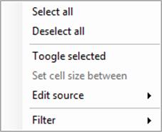
Fig.A 2.1.3.8-2 Mesh levels table context menu.
Right-clicking on the table opens a context menu (Fig.A 2.1.3.8-2). The menu contains the following items:
· Select all – selects all displayed items in the table.
· Deselect all – clears the selection.
· Toggle selected – switches the active status of all selected items. If the status cannot be changed nothing is done. If multiple items with a different activity status are selected all items will be activated.
· Set cell size between – this item is active only when two rows are selected and both of them contain at least one mesh snapping plane. Clicking this item will open a dialogue where maximum cell size can be set. If the dialogue is accepted, all snapping planes from the lower level will force the new cell size value above that level. All snapping planes from the upper level will force the new value below that level.
· Edit source – this item is available if single row is selected and its Source column is not empty. This item opens the sub-menu with a list of border's sources. Clicking on any of the sources in the list will minimise the Inspect window and the modification of the source will begin.
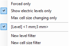
Fig.A 2.1.3.8-3 Filter menu.
Table records can be sorted by level in ascending (default) or descending order. Table records can be also filtered. Active filters can be configured in the table context menu in Filter sub-menu (Fig.A 2.1.3.8-3). The following filter types are available:
· Forced only – if checked only half-cell borders with sources are displayed in the table. By default this filter is enabled.
· Show electric levels only – if checked only electric level are shown (default). Otherwise both electric and magnetic are visible.
· Max cell size changing only – if active only levels at which maximum cell size modification occurs (Up, Down or Both in Force cell size column) are displayed. This option is useful when mesh cell size is configured with mesh Snapping Planes. By default this filter is disabled.
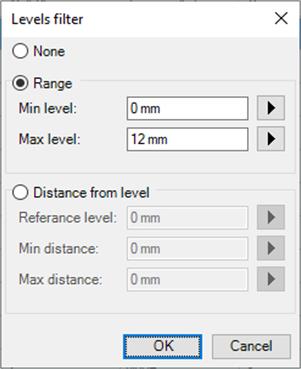
· Level filter – this type of filter displays only records with level value which satisfy a given condition. The conditions are configured with the Levels filter dialogue (Fig.A 2.1.3.8-4). There are two types of conditions available. The Range condition allows definition of minimum and maximum level, only levels between those two values are displayed. In Distance from level filter, reference level, minimal and maximal values are configured. In this case levels shifted from the reference level by a distance varying between minimum and maximum values are displayed. To add new filter click the New level filter from the Filter menu. Active level filters are listed between Max cell size changing only item and New level filter item. They are separated with horizontal lines.
Fig.A 2.1.3.8-4 Levels filter dialogue.
To change or disable the existing filter select an appropriate filter item from the menu. The Levels filter dialogue will be opened (Fig.A 2.1.3.8-4). If filter type is set to None the existing filter will be removed.
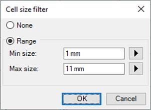
· Cell size filter – if active, only the half-cell borders adjacent to the half-cell of size between the given minimum and maximum are displayed. To add new cell size filter select the New cell size filter item from the filters menu. The filter is configured with the Cell size filter dialogue (Fig.A 2.1.3.8-5). Cell size filters can be modified and removed similarly to the levels filters.
Fig.A 2.1.3.8-5 Cell size filter dialogue.
On the right side of the Inspect dialogue (Fig.A 2.1.3.8-1) two tables are located. The upper table contains the following data about the number of mesh cells in the current project:
o X, Y, Z – number of cells along X, Y and Z axes.
o Geometry – total number of cells in the project.
o With Boundaries – number of cells that will appear in the QW‑Simulator (including the cells needed to model the boundary effects).
The lower table displays information about the smallest half-cell size present in each direction.
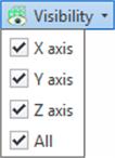
Fig.A 2.1.3.9-1 Mesh visibility drop-down button.
Visibility button allows user to show or hide mesh lines. Each of X axis, Y axis, Z axis check boxes switches mesh visibility in particular direction. All check box configures the visibility for all available axes. For circuits of type 2DV and 2DVcoa Z-axis is disabled, as mesh is not generated along this axis.

Fig.A 2.1.3.10-1 Mesh style drop-down button.
Pressing the Style button shows the mesh styles menu with following options available:
· Use short markers – switches between two types of displaying the mesh. When it is checked (default), the mesh positions are indicating as a short lines. When it is not checked, full mesh lines are displayed.
· Always on the top – enables / disables markers visibility through project objects. Disabled by default.
· Show electric cells – enables / disables electric cells markers visibility. Enabled by default.
· Show magnetic cells – enables / disables magnetic cells markers visibility. Disabled by default.