2.1 2D Window Toolbars
Toolbars provide access to commands in a form of buttons.
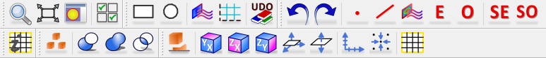
2D Window contains several toolbars with commands needed for definition / modification and 2D visualisation of the project.
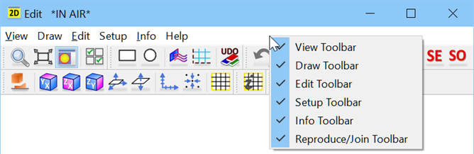
The toolbar’s icons size can be changed in the Preferences dialogue.
Each toolbar can be shown or hidden from the context menu by clicking right mouse button on an empty space near the menu.
View toolbar contains the following commands:
![]() - activates a window zoom. The cursor changes from
- activates a window zoom. The cursor changes from ![]() to
to ![]() and now allows marking a rectangular region to be shown, occupying the window. As an alternative, one can press keyboard Z / Alt+Z to zoom / unzoom the picture around the curros position. Similarly, pressing left mouse button changes the cursor to
and now allows marking a rectangular region to be shown, occupying the window. As an alternative, one can press keyboard Z / Alt+Z to zoom / unzoom the picture around the curros position. Similarly, pressing left mouse button changes the cursor to ![]() and causes that the picture will be dragged following mouse movements.
and causes that the picture will be dragged following mouse movements.
![]() - extents the display to view of the whole structure
- extents the display to view of the whole structure
![]() - switches between isotropic display and fill display
- switches between isotropic display and fill display
![]() - opens 2D View Options dialogue with options for 2D Window display view
- opens 2D View Options dialogue with options for 2D Window display view
Draw toolbar contains the following commands:
![]() - draws a rectangle. The element is being introduced on the current level and with the current height. To change height/level settings please use Define Level dialogue.
- draws a rectangle. The element is being introduced on the current level and with the current height. To change height/level settings please use Define Level dialogue.
![]() - draws a circle or polygon. The element is being introduced on the current level and with the current height. To change height/level settings please use Define Level dialogue.
- draws a circle or polygon. The element is being introduced on the current level and with the current height. To change height/level settings please use Define Level dialogue.
![]() - opens I/O Ports dialogue with options for drawing I/O ports in a manual way
- opens I/O Ports dialogue with options for drawing I/O ports in a manual way
![]() - opens Special Planes and Boundaries dialogue with options for drawing Mesh Snapping Planes and Subregion Borders in a manual way
- opens Special Planes and Boundaries dialogue with options for drawing Mesh Snapping Planes and Subregion Borders in a manual way
![]() - opens the UDO Library dialogue with UDO scripts
- opens the UDO Library dialogue with UDO scripts
Edit toolbar contains the following commands:
![]() - Undo permits to revoke up to N moves in QW-Editor
- Undo permits to revoke up to N moves in QW-Editor
![]() - Redo revokes up to N Undo commands
- Redo revokes up to N Undo commands
![]() - Edit Point is used for moving a point belonging to an element
- Edit Point is used for moving a point belonging to an element
![]() - Edit Line is used for modifying a line belonging to an element
- Edit Line is used for modifying a line belonging to an element
![]() - Edit Port is used for changing port parameters
- Edit Port is used for changing port parameters
![]() - Edit Element allows changing position and parameters of element
- Edit Element allows changing position and parameters of element
![]() - Edit Object allows changing position and parameters of object
- Edit Object allows changing position and parameters of object
![]() - opens Select Element dialogue
- opens Select Element dialogue
![]() - opens Select Object dialogue
- opens Select Object dialogue
Setup toolbar contains the following commands:
![]() - opens Circuit dialogue with options for circuit properties configuration
- opens Circuit dialogue with options for circuit properties configuration
![]() - sets the XY plane
- sets the XY plane
![]() - sets the XZ plane
- sets the XZ plane
![]() - sets the YZ plane
- sets the YZ plane
![]() - opens Define Plane dialogue
- opens Define Plane dialogue
![]() - opens Define Level dialogue
- opens Define Level dialogue
![]() - opens 2D-Axes Settings dialogue
- opens 2D-Axes Settings dialogue
![]() - opens Grid/Snap Parameters dialogue
- opens Grid/Snap Parameters dialogue
![]() - opens Mesh Settings dialogue with options for FDTD mesh configuration
- opens Mesh Settings dialogue with options for FDTD mesh configuration
Info toolbar contains the following commands:
![]() - opens Mesh Info dialogue with information about FDTD mesh
- opens Mesh Info dialogue with information about FDTD mesh
Reproduce/Join toolbar contains the following commands:
![]() - opens Reproduce dialogue, which operates on the group of marked elements
- opens Reproduce dialogue, which operates on the group of marked elements
![]() - performs Cut option that causes the active element to make a hole in the passive one. Active element will not be changed.
- performs Cut option that causes the active element to make a hole in the passive one. Active element will not be changed.
![]() - performs Glue option, which merges the elements. The resulting element will be filled with the medium of the active one.
- performs Glue option, which merges the elements. The resulting element will be filled with the medium of the active one.
![]() - performs Intersect option, which produces one element of the shape being the common part of the passive and active element filled with the medium of the active one.
- performs Intersect option, which produces one element of the shape being the common part of the passive and active element filled with the medium of the active one.