3.2 UDO and project creation
We will now proceed to the UDO and simulation project (*.pro) creation process, where the above rules will be used in practise. This process will be described step by step based on the ant3 scenario from A dielectric antenna.
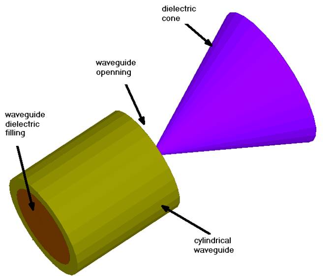
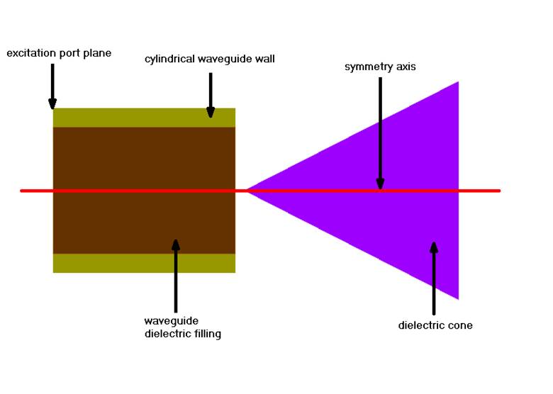
The ant3 structure is a dielectric antenna consisting of cylindrical waveguide filled with dielectric and dielectric cone at the opening of the waveguide, as shown in Fig. 3.2-1. Fig. 3.2-1 (b) and Fig. 3.2-2 present the antenna’s long-section indicating the antenna elements and excitation port plane (Fig. 3.2-1 (b)), and its dimensions (Fig. 3.2-2) with values given in Table 1.
(a)
(b)
Fig. 3.2-1. Dielectric antenna ant3: perspective view (a) and long-section (b).
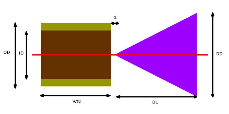
Fig. 3.2-2. Dielectric antenna dimensions.
Table 1 Dielectric antenna parameters’ values.
|
Parameter |
OD |
ID |
WGL |
G |
DL |
DD |
|
Value [mm] |
18 |
14 |
20 |
1 |
23.5 |
24 |
The dielectric materials used in the antenna are characterised by the following parameters:
- Waveguide filling: er= 3.6, μr= 1, s=0, sM=0
- Dielectric cone: er= 2.1, μr= 1, s=0, sM=0
The antenna should be fed by fundamental TE11 circular waveguide mode and is to be analysed in the frequency range from 6 to 20 GHz. In this case we are interested in obtaining reflection coefficient (S11) characteristic in the aforementioned frequency range and radiation patterns at 8 GHz, 10 GHz, and 12 GHz.
The long-section of the antenna is shown because it is crucial for creating the simulation project for QW-V2D. As it has been mentioned in 1, for QW-V2D projects it is required to draw only half of a long-section of the axisymmetrical structure. Thus, in case of ant3 antenna we need to prepare the UDO script, where the antenna structure as in Fig. 3.2-3 is drawn. The symmetry axis should be inserted at y=0 (r=0).

Fig. 3.2-3. Half of antenna’s long-section.
It should be noted at this point that the UDO language allows defining a complete simulation project (meshing, ports, media, post-processings, etc.) in the UDO script and then loading it to QW‑Editor to create the simulation project (*.pro). However it is not mandatory to make those settings through UDO script and they can be easily made in QW-Editor after loading the geometry from UDO script, although there are few things that we recommend to be defined through UDO script and the way of doing this will be described later:
- Media parameters
- Exciting port – the port objects can be found in the UDO library.
- NTF box in case of radiating structures - It defines a virtual surface where the near field to far field transformation, for the purpose of calculating radiation pattern, is performed (the electromagnetic field components at this surface are the subject for this transformation). The NTF box is supplemented with absorbing box, which allows maintaining free space conditions around the radiating structure and in magnetic symmetry plane, which is automatically placed at y=0 (r=0). The NTF box can be found in the UDO library.
Now, when the antenna geometry to be defined (Fig. 3.2-3) is known, we may proceed with the UDO script creation process.