3.8 Introducing symmetry plane
This example is available in .../QW_AddIn_3D/Standard/Various/Wgtocx/wgtocx1_sym.ipt in the QW-AddIn examples directory and can be loaded using File®Open... command from main menu.
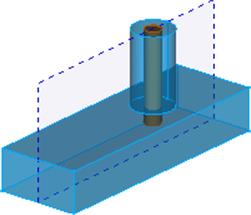
The considered waveguide to coaxial line transition structure is symmetrical and thus we can introduce a symmetry plane in the middle of the structure and simulate only half of it, what significantly speeds up the calculations. For that purpose, in the QuickWave ->Mesh tab we press the Borders ![]() button. The dialogue Mesh borders will appear.
button. The dialogue Mesh borders will appear.
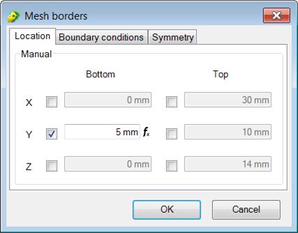
Mesh Borders dialogue setting a symmetry plane at Y Bottom
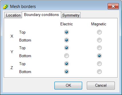
In the Boundary conditions tab we set Magnetic border for Y Bottom position and Electric borders for the rest.
In the Location tab we specify the location of the symmetry at Y bottom position. We change Y bottom value to 5.
In the Symmetry tab we set Y bottom.
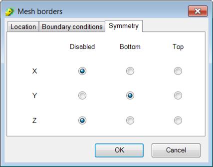
Mesh Borders dialogue settings for introducing symmetry plane at Y Bottom
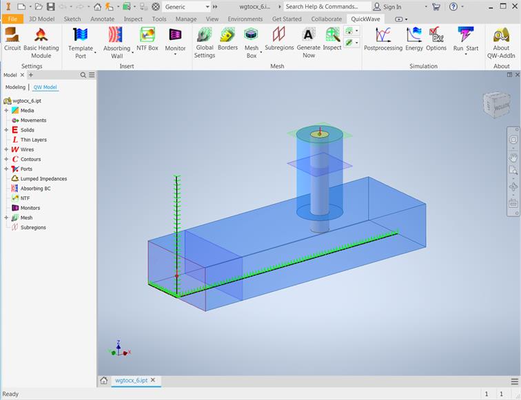
Waveguide to coaxial line transition with symmetry plane.
The project is ready and we can run the simulation. For that purpose we press Start  button from the Simulation section. The QW-Simulator is run and the simulation starts automatically. For a detailed description of QW-Simulator functionalities please refer to QW-Simulator manual.
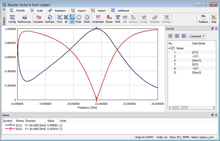
S-parameters calculated for waveguide to coaxial line transition with symmetry plane.
Previous step: Exporting the project and running the simulation.