3.5 Setting up the mesh
Having the structure’s geometry and the ports defined, we can now set up the mesh. To do that, in the ribbon Mesh group we press the Global Settings ![]() button. The following dialogue will appear.
button. The following dialogue will appear.
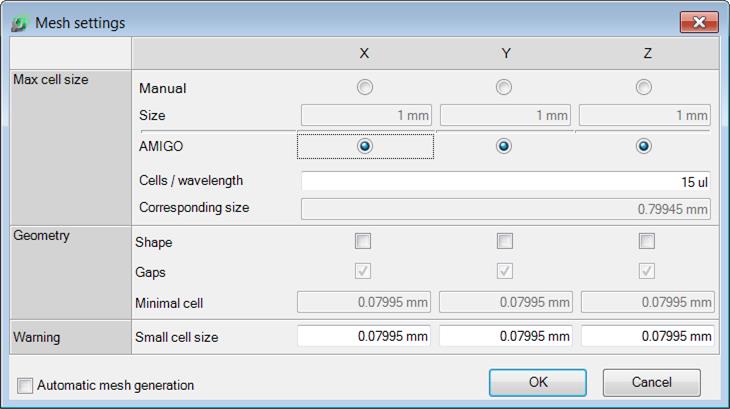
Mesh Settings dialogue with default settings
 .
.
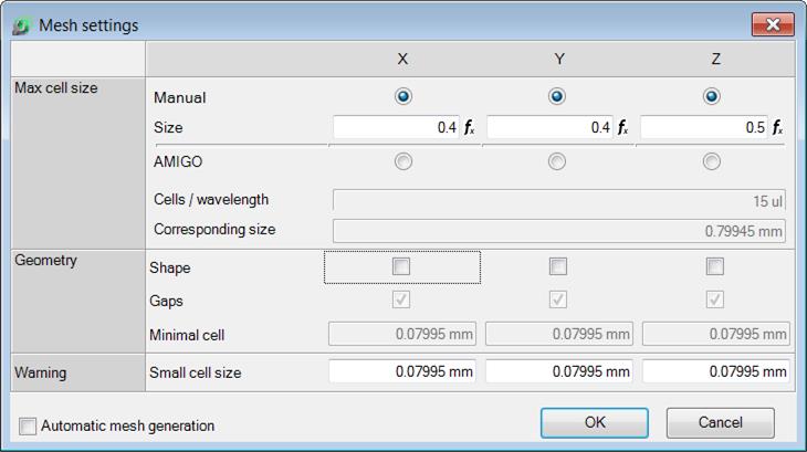
Manual Mesh Settings for waveguide to coax transition
We set the following cell sizes in X, Y and Z direction respectively: 0.4 mm, 0.4 mm and 0.5 mm. The meshing will be enforced in the entire project space.

Waveguide to coaxial line transition with meshing (displayed in short axes visibility mode)
Previous step: Drawing the ports.
Next step: Defining post-processings for simulation.