

|
|

2.3 Drawing the ports
In this step we need to draw and define the ports. In this case we need to define two ports, input and output. The input port will be placed at the waveguide and it will excite the fundamental TE10 mode and the output port with TEM mode will be placed at the coaxial line.To define the ports we need to go to Model tab. As a first one, we will define the waveguide input port. For that purpose we press Templatecommands button and choose Insert Template Source option.
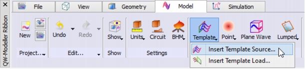 Template commands button.
The following dialogue will appear.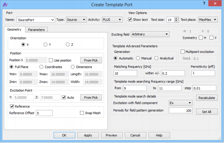 Create Template Port dialogue.
We set the name of the port to SourcePort. The default Type, Activity and Orientation of the port are properly set for this case, thus we may set the port's dimensions. By default the port dimensions will be determined by the maximum structure's dimension. We will now adjust the port dimensions to waveguide cross section. In this case we will set the port dimensions by indicating that it should be placed at waveguide cross section and should inherit its dimensions. We indicate the waveguide wall, where we want the port to be placed, by clicking on the corresponding face. The face will be highlighted.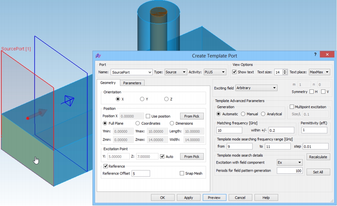 Indication of the face for the port creation.
Then we press From Pick button in the Create Template Port dialogue and the port is adjusted to the waveguide wall.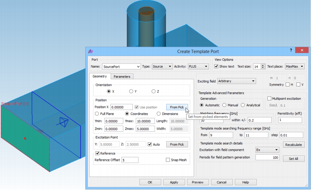 Port adjusted to waveguide cross section using From Pick option.
When the port is drawn we can set its parameters. We leave Reference Offset equal to 5 and switch to the Parameters tab in the Create Template Port dialogue. Fig. 15 shows the Create Template Port dialogue with the settings for our waveguide input port. We excite the structure with a fundamental TE10 mode with a pulse of spectrum between 15 and 25 GHz. Pressing OK button accepts the settings.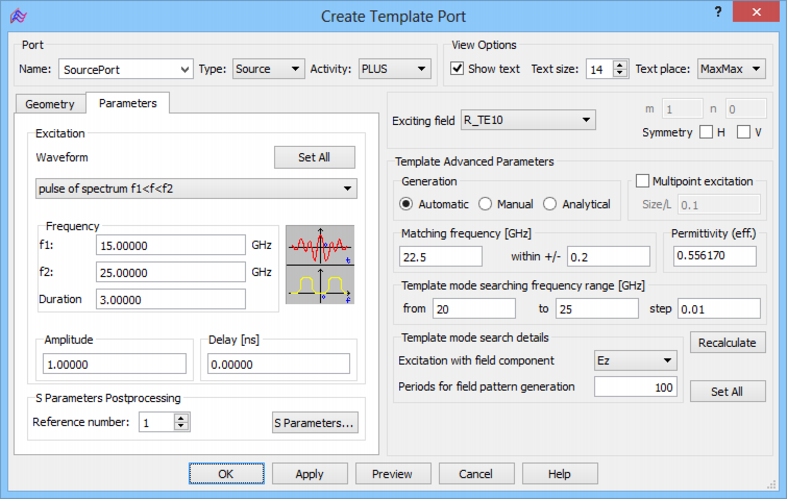 Create Template Port dialogue for the input waveguide port.
In the next step we define the coaxial line output port by pressing Template commands button and selecting Insert Template Load. In this case the Orientation should be chosen to Z direction and the Reference Offset set to 3.5. Indication of the face for the port creation.
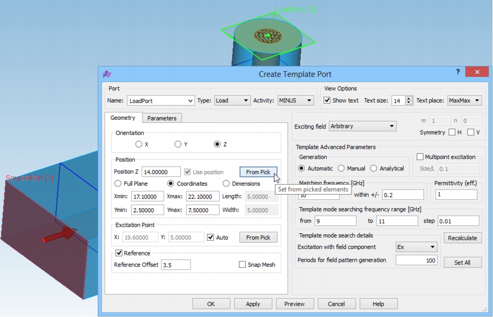 Port adjusted to coaxial line cross section using From Pick option.
We select the face for port placement as previously, but this time we put the port on the coaxial line. We set the TEM mode in the frequency range from 15 to 25 GHz and accept the settings by pressing OK button.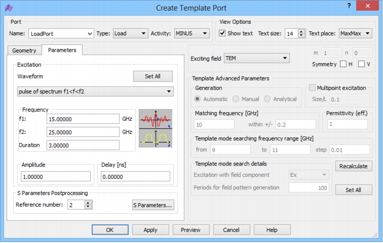 Create Template Port with parameters for coaxial line output port.
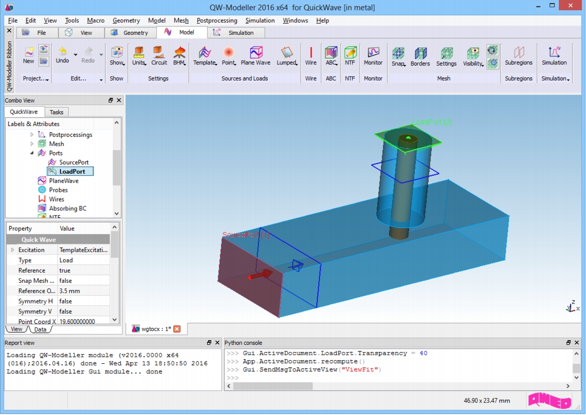 Waveguide to coaxial line structure with ports.
At this stage we can proceed to setting up the mesh.
|
QWED Sp. z o.o. Voice: +48 22 625 73 19 Fax: +48 22 621 62 99 info@qwed.eu |
|
|