

|
|

2.2 Drawing the structure
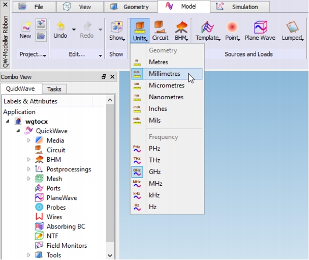
At this stage we will be creating the project geometry. First step that needs to be accomplished is choosing the units that will describe the geometry. To do that we go to Model tab and from Unitsbutton we choose Millimetres.
The scheme of the waveguide to coaxial line transition and the dimensions are shown below. The centre of the coaxial line is placed 19.6 mm from the left edge of the waveguide.
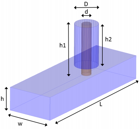 Waveguide to coaxial line transition scheme.
To draw the structure we go to Geometry tab. Let us start from drawing the air filled waveguide. As it was stated in Step 1, we need to draw only the inside of the structure (the surrounding medium is metal), thus we start from the air block, which stands for the waveguide inside. To draw the waveguide we press Create a Boxbutton in the Primitives section and a dialogue appears.
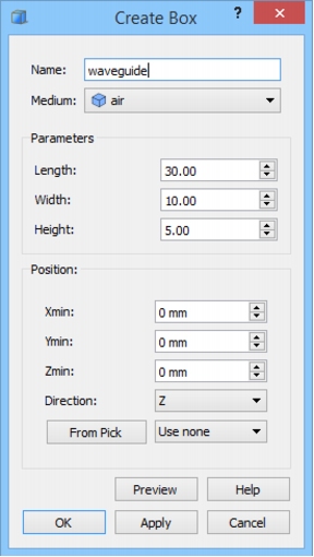 Create Box dialogue for waveguide object.
In the Name field we put the name of the object and from the Medium combo box we choose air. Now we can proceed to setting the waveguide dimensions according to the table above. With Position set to (0,0,0) the waveguide will be drawn so that its lower right corner is placed at this coordinates. After pressing OK button the waveguide object appears in the project.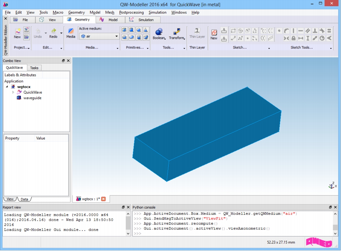 QW-Modeller project window with waveguide object.
For better visualisation of the inside of the waveguide, we change its transparency by selecting waveguide object on the Tree View, and changing Transparency in the View tab in Property Editor to 50.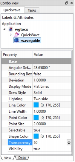 Waveguide transparency.
In the next step we draw the inner conductor of the coaxial line. To do that we press Create a Cylinderbutton from the Primitives section and the dialogue appears.
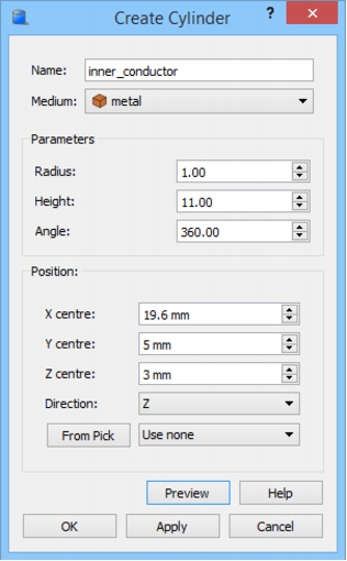 Create Cylinder dialogue for inner conductor object.
We name the object as inner_conductor and set its medium to metal. We assign its dimensions according to the above table and set its position to X= 19.6 mm, Y= 5 mm and Z= 3 mm. Those coordinates assure that the centre of the inner conductor is spaced from the left waveguide edge by a distance of 19.6 mm, is placed in the centre of waveguide width and is inserted into the waveguide for 2 mm. After pressing OK button we get the following structure.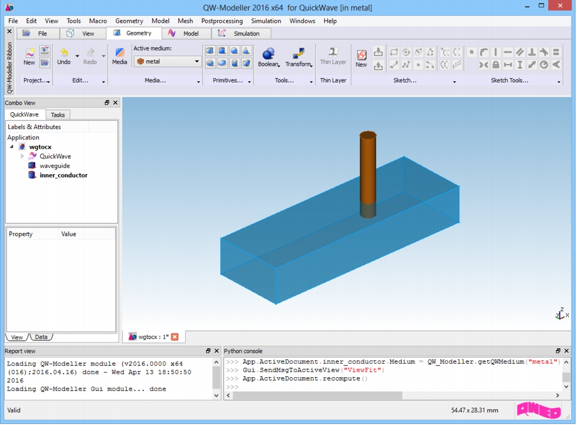 QW-Modeller project window with waveguide and inner conductor objects.
Now we can draw the air filling of the coaxial line. For the second time we invoke Create Cylinder dialogue and we set up the parameters for the filling.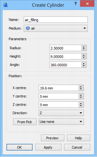 Create Cylinder dialogue for air filling of the coaxial line.
We set the name to air_filling and choose the air medium for the object. The dimensions are set according to the table and Position parameters are chosen so that they assure proper placement of the object with respect to the waveguide. Pressing OK button gives us full structure of the waveguide to coaxial line transition.
For better visualisation, we change the transparency of the air_filling object by selecting it on the Tree View, and changing Transparency in the Property Editor to 50.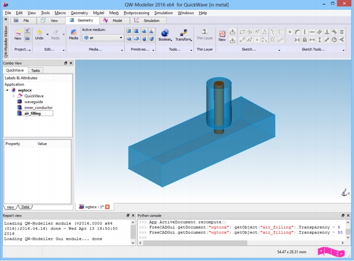 QW-Modeller project window with waveguide to coaxial line transition.
Having the geometry of the structure ready we can proceed to the next step.
|
QWED Sp. z o.o. Voice: +48 22 625 73 19 Fax: +48 22 621 62 99 info@qwed.eu |
|
|