

|
|

19 Patch antenna
This example is available in .../QW-3D/Standard/Antennas/Patch/patch1.QWPro in the QW-Modeller examples directory and can be loaded using File®Open Examples... command from main menu.
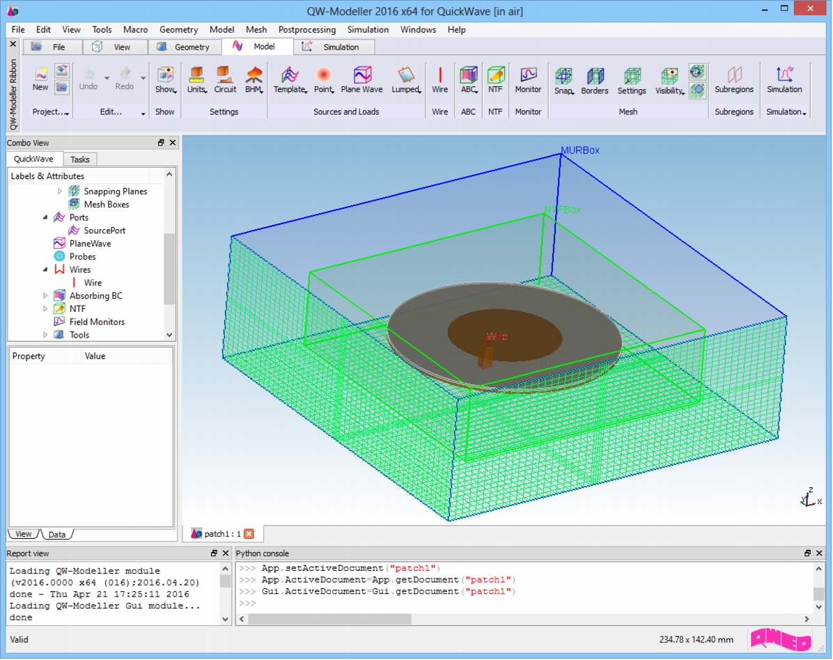
General DescriptionA circular patch antenna.
GeometryThe geometry of the antenna consists of circular base with diameter of 86mm and 1 mm height made of PEC, circular dielectric plate with height of 0.787mm and diameter of 86mm made of teflon and infinitely thin (0 mm in thickness) circular patch of 42mm in diameter.The model is surrounded by superabsorbing (MUR) box.In practical designs it often happens that a patch antenna is fed with a vertical coaxial line. Such a line may have a very small diameter, when compared to the dimensions of the patch and to the considered wavelengths. In such a case it would be impractical to mesh the cross-section of the line into sufficiently small FDTD cells reproducing accurately the cylindrical shape of the conductors. This would unnecessarily provoke a drastic increase in the overall computing time of the project.Thus in patch1.pro a different approach is used. The cross-section of the dielectric filling of the coax is approximated by a rectangular shape composed of four FDTD cells. In the centre we place a wire. The diameter of the wire is chosen so that the characteristic impedance of the line adopts the desired value (in our case 50 W).
Post Processing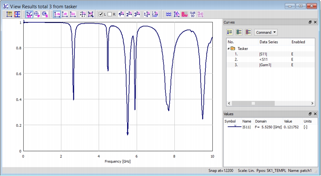 Reflection coefficient of the wire antenna.
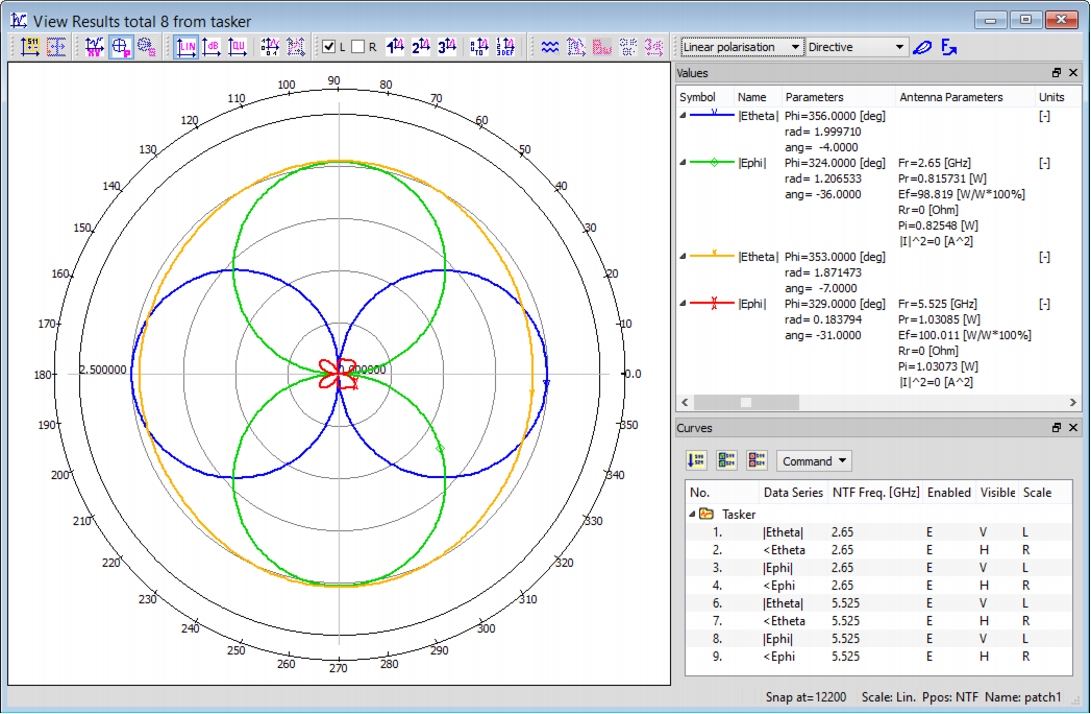
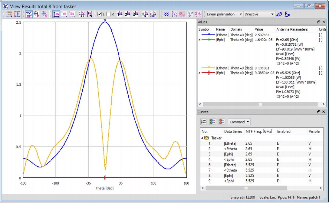 Radiation patterns versus elevation angle Theta with azimuthal angle Phi=0, calculated for two frequencies: 2.65 GHz and 5.525 GHz
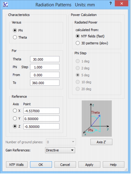
 Radiation patterns versus azimuthal angle Phi with elevation angle Theta=30° calculated for two frequencies: 2.65 and 5.525 GHz.
|
QWED Sp. z o.o. Voice: +48 22 625 73 19 Fax: +48 22 621 62 99 info@qwed.eu |
|
|