9 Subregions
In QW-Simulator MultiGPU, the user establishes how many devices will be used for particular project calculation. The decision is made beforehand. Every device is running its own part of the project called Subregion. User can create them by adding in editor of choice a plane called Subregion Border. Project exported with Subregions can be simulated only in QW-Simulator MultiGPU. To run simulation using other simulator than QW-Simulator MultiGPU, the partitioning should be turned off in Export Options dialogue and project needs to be re-exported (see Export Options chapter for more information).
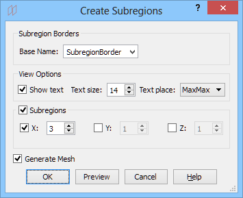
Create Subregions
The Create Subregions dialogue for creating subregions can be invoked:
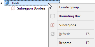
· with the ![]() command from Tools group context menu in the Tree View
command from Tools group context menu in the Tree View
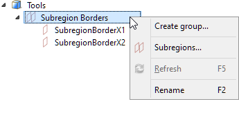
· with the ![]() command from Subregion Borders group context menu in the Tree View
command from Subregion Borders group context menu in the Tree View
· with the Model->Subregions… command from main menu
Subregion Borders are allowed along one direction only (X, Y or Z). If the creation of Subregion Borders is restricted, the proper message will appear in the Report View window.
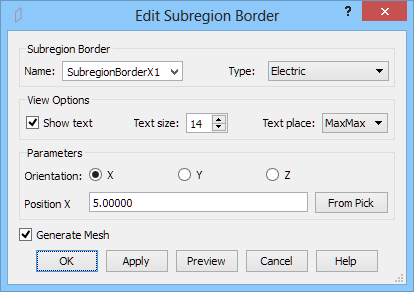
Edit Subregion Border
The Edit Subregion Border dialogue for editing subregion border can be invoked:
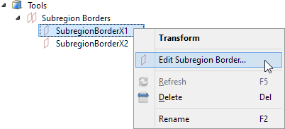
· with the ![]() command from the selected subregion border context menu in the Tree View
command from the selected subregion border context menu in the Tree View
· with the doubleclick on the selected subregion border in Subregion Borders group in the Tree View
Python code
The python code generated by Create Subregions dialogue for four Subregions (three Subregion Borders needed) in X direction:
from FreeCAD import Base
QW_Modeller.addQWObject("QW_Modeller::SubregionBorder","SubregionBorderX1")
App.ActiveDocument.SubregionBorderX1.Placement = Base.Placement(Base.Vector(5.0000000,5.0000000,5.0000000),Base.Rotation(0.5000000,0.5000000,0.5000000,0.5000000))
App.ActiveDocument.SubregionBorderX1.Orientation = "X"
App.ActiveDocument.SubregionBorderX1.Position = 5.00000
App.ActiveDocument.SubregionBorderX1.AutomaticBorder = True
App.ActiveDocument.SubregionBorderX1.Length = 10.00000
App.ActiveDocument.SubregionBorderX1.Width = 10.00000
Gui.ActiveDocument.SubregionBorderX1.ShowText = True
Gui.ActiveDocument.SubregionBorderX1.TextSize = 14
Gui.ActiveDocument.SubregionBorderX1.TextPlace = 3
from FreeCAD import Base
QW_Modeller.addQWObject("QW_Modeller::SubregionBorder","SubregionBorderX2")
App.ActiveDocument.SubregionBorderX2.Placement = Base.Placement(Base.Vector(7.0000000,5.0000000,5.0000000),Base.Rotation(0.5000000,0.5000000,0.5000000,0.5000000))
App.ActiveDocument.SubregionBorderX2.Orientation = "X"
App.ActiveDocument.SubregionBorderX2.Position = 7.00000
App.ActiveDocument.SubregionBorderX2.AutomaticBorder = True
App.ActiveDocument.SubregionBorderX2.Length = 10.00000
App.ActiveDocument.SubregionBorderX2.Width = 10.00000
Gui.ActiveDocument.SubregionBorderX2.ShowText = True
Gui.ActiveDocument.SubregionBorderX2.TextSize = 14
Gui.ActiveDocument.SubregionBorderX2.TextPlace = 3
App.ActiveDocument.recompute()
Gui.SendMsgToActiveView("ViewFit")