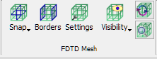
6 FDTD Mesh
Mesh refers to the set of FDTD cells. These cells of cubicoidal (or cubicoidal cut by a plane) shape have the basic size defined through the Mesh Settings dialogue. However, the actual cell size may be modified downwards by the software to fill the area between mesh snapping planes or inside the mesh boxes with an integer number of cells. Mesh snapping planes or mesh boxes are either introduced explicitly by the user (via Snapping Plane or Mesh Box dialogues) or forced automatically by the QW-Modeller (for example, at horizontal boundaries of the objects).
The user is recommended to verify the actual settings of the mesh and special planes (in the Mesh Inspect dialogue) before running the simulation. If two snapping planes are accidentally introduced too close to each other, they force a small FDTD cell, which leads to a small time step, and hence prolongs the simulation time. To warn the user about the existence of such closely situated special planes, they will be marked by red points at the external contour of the grid.
The electric or magnetic project boundaries as well as symmetries can be set in the Boundary Conditions dialogue.
Various visualisation options of the FDTD Mesh are described in the Mesh Visualisation chapter.
A detailed discussion regarding FDTD Mesh is given in Mesh.
In QW-Simulator, the Test Mesh window allows watching and testing the effective FDTD mesh grid (Effective FDTD mesh grid) and coefficients used in FDTD simulation (Conformal FDTD algorithm parameters).