3.2 Mode TE11
Each waveguide mode is described by unique distribution of transverse and longitudinal components of the electric and magnetic fields. Similarly to rectangular waveguides, two kinds of waveguide modes are recognised in case of circular waveguides: TE and TM. The waveguide mode in circular waveguide is described with m and n indexes, which stand for the field variation in radial and axial directions respectively.
In case of circular waveguides the fundamental mode is TE11.
In this part, the distribution of transverse and longitudinal fields’ components of TE11 mode is investigated. For fields’ visualisation the QuickWave software is used.
The circular waveguide with radius of 10 cm and the length of 30 cm is considered. The model of such waveguide cir.QWpro can be loaded in QW-Modeller. The cutoff frequency of TE11 mode in this waveguide is 0.879 GHz. The waveguide is excited at 1 GHz and its length is around half of a guide wavelength.
Run the electromagnetic simulation with QuickWave using Start ![]() button in Simulation tab (Fig. 3).
button in Simulation tab (Fig. 3).

Fig. 3 Simulation tab in QW-Modeller.
Press ![]() button in 2D/3D Fields tab of QW-Simulator to open fields visualisation window. The consecutive displays shown in Figs. 4-9 may be viewed by pressing
button in 2D/3D Fields tab of QW-Simulator to open fields visualisation window. The consecutive displays shown in Figs. 4-9 may be viewed by pressing ![]() button for several times (once for obtaining each of the following displays). For the visualisation convenience the display windows may be maximised.
button for several times (once for obtaining each of the following displays). For the visualisation convenience the display windows may be maximised.
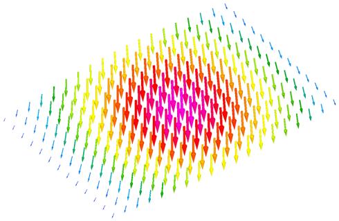
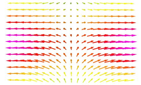
In case of TE11 mode, both radial and axial components of transverse fields exists (m, n idexes are non-zero), resulting in the distribution of total electric and magnetic field in the waveguide’s cross section as shown in Fig. 4 and Fig. 5 respectively. The following pictures show the displays of electric and magnetic fields along the waveguide. It is clearly seen that there is no longitudinal component (in the direction of wave propagation – Z direction) of the electric field and there is longitudinal magnetic field only in this case. The displays confirm the waveguide’s length to be half of guide wavelength since one wave half can be recognised along waveguide.
The fields’ distribution displayes are given for a randomly chosen time moment. When the simulation results are observed on-line the fields variations as the wave is passing the waveguide will be observed.
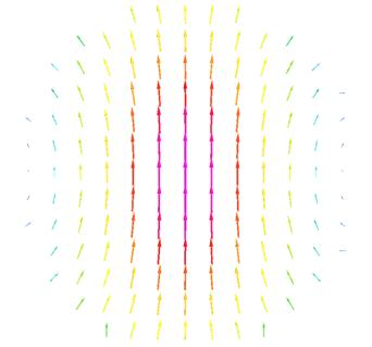
Fig. 4 A distribution of electric field for TE11 mode in a cross section of circular waveguide (YX plane).
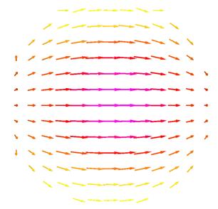
Fig. 5 A distribution of magnetic field for TE11 mode in a cross section of circular waveguide (YX plane).

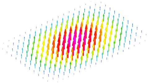
Fig. 6 A distribution of electric field for TE11 mode in circular waveguide (XZ plane – in the middle of the waveguide).
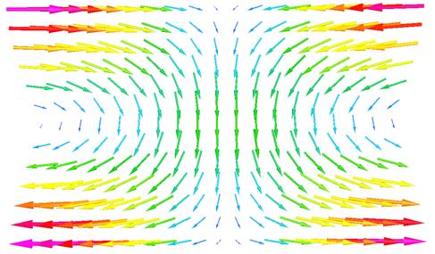
Fig. 7 A distribution of magnetic field for TE11 mode in circular waveguide (XZ plane – in the middle of the waveguide).
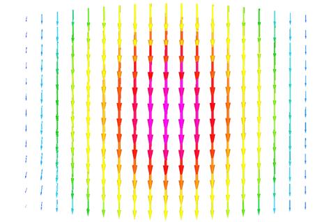
Fig. 8 A distribution of electric field for TE11 mode in circular waveguide (YZ plane – in the middle of the waveguide).
(a)
(b)
Fig. 9 A distribution of magnetic field for TE11 mode in circular waveguide (YZ plane): in the middle of the waveguide (a) and near the waveguide wall (b).