2.8 Using QW-V2D with QW-OptimiserPlus
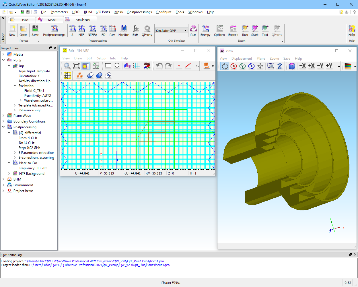
Consider Opt_Plus/Horn4/horn4.pro example (also available in Standard/Antennas/Horn4/horn4.pro). It has been prepared using elib/V2Dhorns/horn4.udo. It concerns another kind of axisymmetrical corrugated horn. Longitudinal half-section of the structure in 2D window is presented in Fig. 2.8‑1. The meshing has been generated with the help of AMIGO assuming 25 cells per wavelength at the uppermost frequency of 14 GHz. The assumed parameters are the default parameters of anthorn.udo. The user is encouraged to try and modify them. Among the parameters which can be changed are: width, depth and number of corrugations, angle of opening of the conical shape of the horn and the dimensions of the waveguide step introduced for better matching of particular frequency bands. This range of changes of parameters makes the horn4.pro example quite practical. It can be used to design a simple compact feed horn for paraboloidal reflector antenna (e.g. for satellite TV reception).
Run the project with default parameters. The results of simulations of |S11| and radiation patterns at 11 GHz are presented in Fig. 2.8-2. Note that we have displayed the antenna patterns with the option of Relative gain. We have a choice of different scales for antenna patterns discussed in Antenna Gain.
Fig. 2.8-1 Meshing in horn4 example.
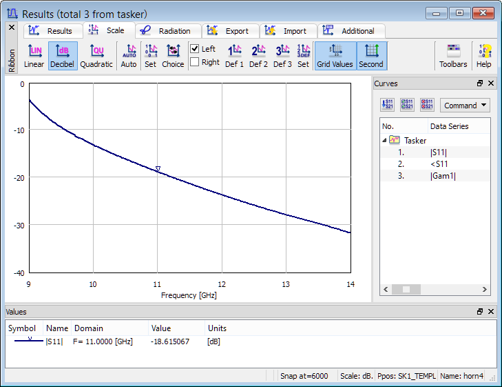
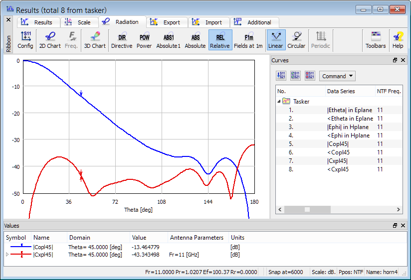
Fig. 2.8-2 Reflection coefficient and radiation patterns of horn4 example.
The antenna parameters displayed in Fig. 2.8-2 are relatively good but we may wish to improve them with respect to particular criteria. Assume the following requirements:
- reflections in the band between 10.5 and 11.5 GHz at the level of 0.05 (-26 dB) or better,
- main beam width at 11 GHz measured at the level of 0.316 (-10 dB) equal to ± 45º,
- crosspolar at 11 GHz, in the entire range of angles, lower than 0.05 (-26 dB).
It can be seen in Fig. 2.8-2 that only the last of the three requirements is fulfilled by the original design.
Let us now run optimisation of the horn using QW-OptimiserPlus. We open the horn4.pro example in QW-Editor, press ![]() and double-click over horn4.udo. The horn4.udo header opens as shown in Fig. 2.8-3. When looking at the parameters displayed in the header we need to consider two important rules of functioning of QW-OptimiserPlus:
and double-click over horn4.udo. The horn4.udo header opens as shown in Fig. 2.8-3. When looking at the parameters displayed in the header we need to consider two important rules of functioning of QW-OptimiserPlus:
- The name of the UDO object containing the parameters to be changed during optimisation must be the same as the name of the project file. This is the case here since both are named horn4.
- During the optimisation process, all the UDO parameters, which are not variables of optimisation, will have constant values as at the last Save or Export command for the project. Thus Fig. 2.8-3 displays the actual values of those parameters except for parameters No. 4, 5, 7, 8 and 10 which will be changed during optimisation (as shown further in this Section).
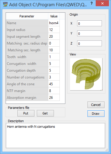
Fig. 2.8-3 horn4.udo header.
Now press ![]() to save the current version of the project and
to save the current version of the project and ![]() to export the project and open QW-Simulator. In QW-Simulator we open Configure Optimiser (
to export the project and open QW-Simulator. In QW-Simulator we open Configure Optimiser (![]() button). We can see three variants of the dialogue as presented in Fig. 2.8-4, Fig. 2.8-6 and Fig. 2.8-7.
button). We can see three variants of the dialogue as presented in Fig. 2.8-4, Fig. 2.8-6 and Fig. 2.8-7.
In Fig. 2.8-4 we can see the Objectives tab. Four objectives have been defined according to the requirements presented earlier in this Section:
- |S11| in the band of 10.5 to 11.5 GHz is supposed to be as low as possible but any value below 0.05 is acceptable (Upper field). This means that when the maximum value of |S11| in the considered band equals to |S11|max, it will generate the value of the goal function for this objective equal to (|S11|max -0.05)/0.05.
- The Copolar45 relative gain in the range of angles between 0º and 45º should be higher than 0.3 and the goal function for this objective will be calculated as (0.3-|Copl45|min)/(0.316-0.3).
- The Copolar45 relative gain in the range of angles between 45ºand 180º should be smaller than 0.33 and the goal function for this objective will be calculated as (|Copl45|max-0.33)/(0.33-0.316).
- The Crosspolar45 relative gain in the range of angles between 0º and 180º should be smaller than 0.05, and the goal function for this objective will be calculated as (|Cxpl45|max-0.05)/0.05.
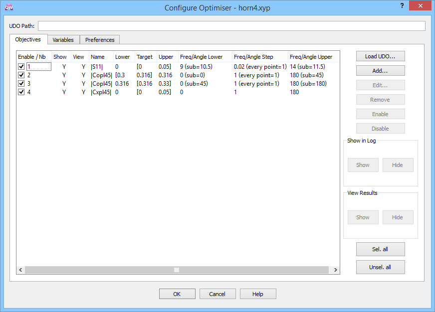
Fig. 2.8-4 Objectives for horn4 example displayed in Configure Optimiser dialogue.
During the optimisation the highest value of the goal functions for individual objectives will be taken as the value of the overall goal function.
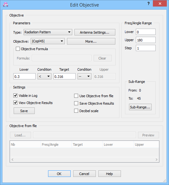
Fig. 2.8-5 Editing of one of the objectives of horn4.udo.
A new objective can be added by pressing ![]() . Each of the existing objectives can be individually edited after highlighting it and pressing
. Each of the existing objectives can be individually edited after highlighting it and pressing ![]() . Fig. 2.8-5 presents the dialogue used to edit the second objective. After pressing
. Fig. 2.8-5 presents the dialogue used to edit the second objective. After pressing ![]() we can define (or change) the parameters used in the extraction of radiation patterns. In particular, we can specify what kind of characteristic is of interest (Relative gain in the considered case) and which of the frequencies is of interest. Here we have just one frequency (11 GHz) defined in the Near To Far dialogue of QW-Editor. In general, several frequencies may be set inQW-Editor and we will need to choose one to be taken for the particular objective. We also specify the angle range and step for radiation pattern calculations (0º to 180º with a step of 1º). Note that after getting back to the Objective dialogue (see Fig. 2.8-4) we should specify what subrange of that range is to be taken for calculation of the objective (from 0º to 45º in the considered case).
we can define (or change) the parameters used in the extraction of radiation patterns. In particular, we can specify what kind of characteristic is of interest (Relative gain in the considered case) and which of the frequencies is of interest. Here we have just one frequency (11 GHz) defined in the Near To Far dialogue of QW-Editor. In general, several frequencies may be set inQW-Editor and we will need to choose one to be taken for the particular objective. We also specify the angle range and step for radiation pattern calculations (0º to 180º with a step of 1º). Note that after getting back to the Objective dialogue (see Fig. 2.8-4) we should specify what subrange of that range is to be taken for calculation of the objective (from 0º to 45º in the considered case).
In the dialogue of Fig. 2.8-4 we also decide which objectives will be Shown in the Simulator Log window and which of them will be viewed in a separate Results window. The entire calculated range will be displayed in Results window.
Now consider the Variables tab of the optimisation as displayed in Fig. 2.8-6. When we configure the QW-OptimiserPlus for a new project, we first need to Load UDO. In that operation we browse the directories to choose the proper UDO file. The software displays all the parameters of that UDO and their default values as found in the UDO script. When horn4.ud3 file exists in the project directory, values of variables from this file prevail over the default values from the UDO script. Then we Enable the parameters which are supposed to be changed during the optimisation. We set their initial Value, the Lower bound, the Upper bound and the Resolution. The Resolution indicates that we expect such a change of variable to be insignificant. If a set of new values of the variables proposed by the QW‑OptimiserPlus differ within resolution from those in one of the formerly used sets, the simulation will not be run.
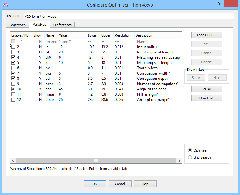
Fig. 2.8-6 Variables for horn4 example displayed in Configure Optimiser dialogue.
During the optimisation the values of variables adopted for the particular QW-Simulator run and the values of calculated objectives are stored in Optimiser Cache. The information stored in the Cache is used by QW-OptimiserPlus to decide upon the next set of variables to be tried while avoiding unproductive recalculation of the states for which the goal function has already been calculated. Thus when the Cache for the particular project exists, and the Initial values of optimised variables have not been recently modified by the user, the QW-OptimiserPlus starts its next run from the best state found in the Cache. In the lower part of the dialogue of Fig. 2.8-6 we can see the information about that. If we do not want the software to use the Cache, we need to invoke Clear command in the Optimiser tab of QW-Simulator. After returning to the dialogue of Fig. 2.8-6 we will see the information that there is No cache file and the optimisation will start from the initial values declared in the variable list.
Important note: Most changes in the project or Configure Optimiser settings make the existing Cache invalid. The Optimiser cache chapter specifies in which cases the cache needs to be cleared by the user to avoid confusing results.
Fig. 2.8-7 presents the Preferences tab defined in the Configure Optimiser dialogue. In the upper part we have a set of parameters for communication of QW-OptimiserPlus with other programs. Normally, the user does not need to change them and can rely on default settings. Advanced users may refer to QW-OptimiserPlus manual for more information. The user needs to set proper values only in two sections of the Preferences tab: Simulations and Stop criteria.
In Simulations we need to specify how many FDTD iterations will be performed during each run of QW-Simulator. This should be based on the user’s experience with a single run of the considered project. When running horn4.pro we can see that the S-parameter results stabilise after about 5000 iterations. With some additional margin we have put 7000 into the QW‑OptimiserPlus Preferences.
In Stop Criteria we have set 300 as the maximum number of simulations performed and 0 as the level of the goal function, which terminates the optimisation. Level 0 means that all the Objectives have been reached. Sometimes the goal function stabilises at a certain minimum level above 0. In such a case, we know that this is a local minimum of the goal function but cannot be sure that other lower minimum does not exist. If the box: Stop when Goal Function Stabilises within Tolerance .. is checked, the optimising process will stop at the reached local minimum. Otherwise QW‑OptimiserPlus will try to jump out of that minimum in a search for other minima. It may succeed although there is no guarantee that it will. In the latter case, the process will stop on Maximum Number of Simulations Performed.
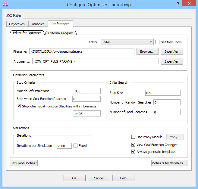
Fig. 2.8-7 Preferences for horn4 example displayed in Configure Optimiser dialogue.
Start the optimisation by pressing ![]() button. QW-Simulator opens six windows: Simulation Log, Results window for S11, two Results windows for 2D radiation pattern results for Copl45 (with the same results of simulation but marking different targets and bounds of the two objective), Results window for 2D radiation pattern for Cxpl45 and Goal Function Results window. After 43 runs of QW-Simulator, QW-OptimiserPlus stops and informs: Target objective function value reached (see Fig. 2.8-8). We can also see the optimal set of variables. The best run (number 42) is marked by an asterisk in the Simulation Log.
button. QW-Simulator opens six windows: Simulation Log, Results window for S11, two Results windows for 2D radiation pattern results for Copl45 (with the same results of simulation but marking different targets and bounds of the two objective), Results window for 2D radiation pattern for Cxpl45 and Goal Function Results window. After 43 runs of QW-Simulator, QW-OptimiserPlus stops and informs: Target objective function value reached (see Fig. 2.8-8). We can also see the optimal set of variables. The best run (number 42) is marked by an asterisk in the Simulation Log.
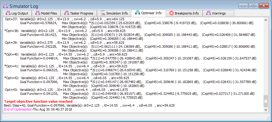
Fig. 2.8-8 Fragment of the Simulator Log window generated during optimisation of horn4 example.
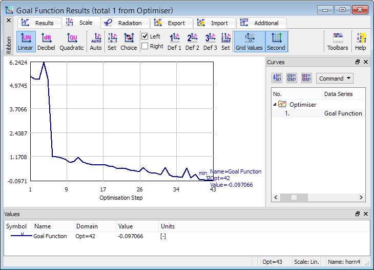
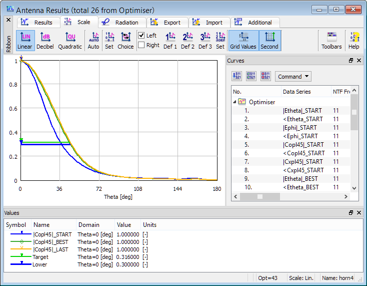
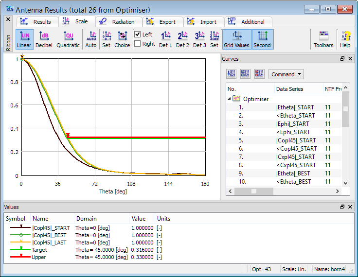
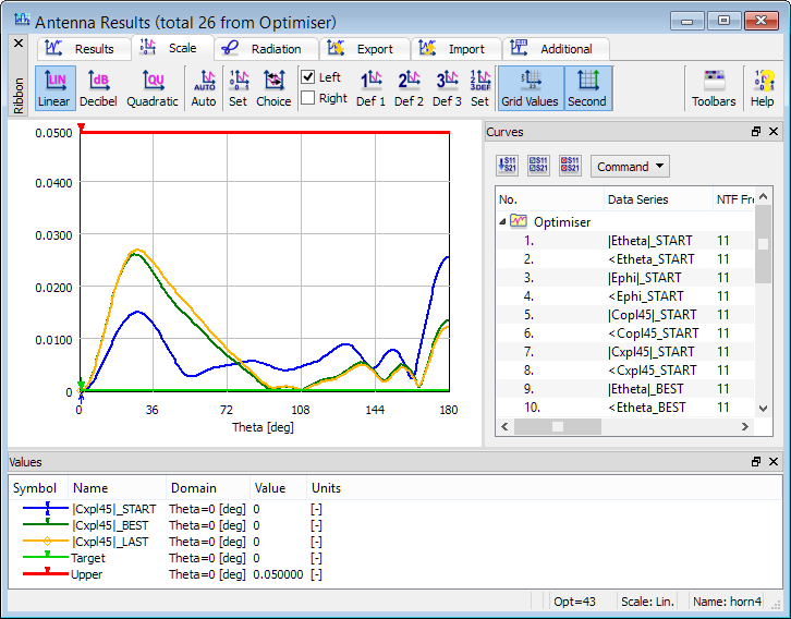
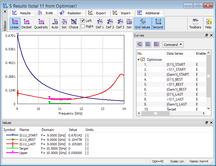
Fig. 2.8-9 Results of optimisation of horn4 example.
Fig. 2.8-9 presents the display of simulation results for the Start, Best and Last run in the optimisation process as well as the evolution of the Goal Function. It can be noted that the minimum of |S11| has moved to the requested frequency 11 GHz. The width of the main beam has been adapted to the requirements. The crosspolar characteristic is slightly worse than at the starting point but it meets the requirements anyway.