2.9.2 Radiating horn with lens
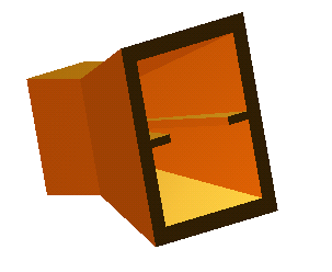
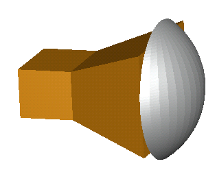
Let us consider another example, which will illustrate the application of library biphased objects. It concerns a rectangular waveguide ridged radiating horn with a teflon lens in front of it, as presented in Fig. 2.9.2-1. We can see a separate picture of the horn as well as the horn associated with the lens. The corresponding project is stored in standard example directory under a name ..\Antennas\holen\holen1.pro.
Fig. 2.9.2-1 Ridged horn (left) and the same horn accompanied by a teflon lens (right).
Let us look at the UDO script examples\holen.udo, which comprises the horn, the lens, and the NTF box:
comment="Rectangular ridged horn + lens + NTF box";
bitmap="holen0.bmp";
PAR("object name", oname, holen);
PAR("waveguide length (wl)",wl,10);
PAR("horn width (hw)",hw,15);
PAR("horn height (hh)",hh,20);
PAR("horn length (hl)",hl,15);
PAR("wall thickness (wt)",wt,2);
PAR("ridge height",rt,1);
PAR("waveguide ridge width",rhw,1);
PAR("horn ridge width",rhh,5);
PAR( "inp-to-ref-dist (inrd)",inrd,5);
PAR( "port IOP file",pio,inp);
PAR("lens radius",lr,15);
PAR("horn-to-lens distance",htl,0);
PAR("lens thickness",lth,7);
PAR("lens-to-ntf distance",lntf,3);
PAR("ntf-to-absorbing distance",antf,5);
ENDHEADER;
lmed="teflon";
ww=5;
wh=10;
TEST( hw > 0, " Width should be positive" );
TEST( hh > 0, "Height should be positive" );
TEST( wl > 0, "Length should be positive" );
TEST( hl > 0, "Length should be positive" );
TEST( wt > 0, "Thickness should be positive");
TEST( htl>= 0, "Horn-to-lens distance cannot be negative");
TEST( lr>lth,"Lens radius must be bigger than its thickness");
OPENOBJECT(oname);
CALL("antennas/horn1hr.udo", oname, ww, wh, wl, hw, hh, hl, wt, rt, rhw, rhh, inrd, pio, "X", x, y, z, 18);
CALL("lenses/lpc1.udo", "lens", lr, lth, lmed, 16, "Y", 2, 0, x+hl+htl, y, z, 12);
# calculation of maximum dimensions of the structure in Y and Z directions
lenh=sqrt(lth*(2*lr-lth));
ymax=2*lenh;
if (0.5*hw+wt)>lenh do ymax=hw+2*wt; endif;
zmax=2*lenh;
if (0.5*hh+wt)>lenh do zmax=hh+2*wt; endif;
# calculation of ntfbox size
xntf=wl+hl+lth+2*lntf;
yntf=ymax+2*lntf;
zntf=zmax+2*lntf;
CALL("boxes/ntf.udo", xntf+2*antf, yntf+2*antf, zntf+2*antf, xntf, yntf, zntf, N, N, N, x-wl-lntf-antf, y-0.5*yntf-antf, z-0.5*zntf-antf, 13);
CLOSEOBJ;
Here are some remarks about the UDO script presented above:
· It is essentially composed of three calls to other library UDOs, each of them used to draw one of the objects: the horn, the lens, and the NTF box. These three calls are supplemented by some algebraic operations needed to calculate the appropriate positions of the NTF surface and absorbing boundaries.
· As it has been mentioned in Using standard library UDOs to create more complicated UDOs, the most convenient way to produce a CALL command is by copying it from the Description of the library object to be called. Then the default variables can be changed to the variables or expressions appropriate for the master UDO.
· Note that not all the variables need to be declared in the header. Those which we do not intend to change in the project can simply be declared in command lines like: lmed="teflon"; ww=5; wh=10.
Note that horn1hr.udo is a monophased object while lpc1.udo is a biphased object. In the DRAFT phase horn1hr.udo enforces several mesh snapping planes. Most important are those at the boundaries along the horn ridges. They help to ensure maximum accuracy of QW-3D analysis enhanced by special singularity models at sharp metal edges. In other words, it is the horn that should decide about the meshing. The lens produced by a biphased object adapts its curvature approximation to the current meshing. In the FINAL phase it is composed of combined elements – each of them of the height of the current FDTD sublayer. Thus the system of biphased meshing assures the optimum conformal approximation for all the objects involved.
holen1.pro is ready to be used. We will not discuss here the results of the analysis, but please try to run it. It is interesting as a tutorial exercise.