2.8.1 A structure of UDO libraries
QW-3D offers a system of User Defined Libraries containing a wide variety of UDO scripts useful in simulation project preparation.
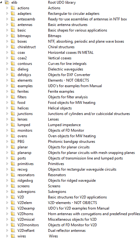
Fig. 2.8.1-1 UDO libraries subdirectories.
At the time of release of version 2023 the system contains about 500 UDOs grouped in the libraries of Fig. 2.8.1-1. It is expected to continuously expand in the future. The libraries directory, further called also elib, opens upon pressing ![]() button in the 2D Window of QW-Editor. The appearing window with elib directory and descriptions of subdirectories is shown in the Fig. 2.8.1-2. A default path is set to elib directory and thus the software displays the all the subdirectiories contained in elib. We can use UDOs of other directories by choosing it from the directory tree. After selecting the subdirectory basic we can see that it contains some UDOs and in the lower part of every one we can read its short description: Element of a vertical cylinder.
button in the 2D Window of QW-Editor. The appearing window with elib directory and descriptions of subdirectories is shown in the Fig. 2.8.1-2. A default path is set to elib directory and thus the software displays the all the subdirectiories contained in elib. We can use UDOs of other directories by choosing it from the directory tree. After selecting the subdirectory basic we can see that it contains some UDOs and in the lower part of every one we can read its short description: Element of a vertical cylinder.
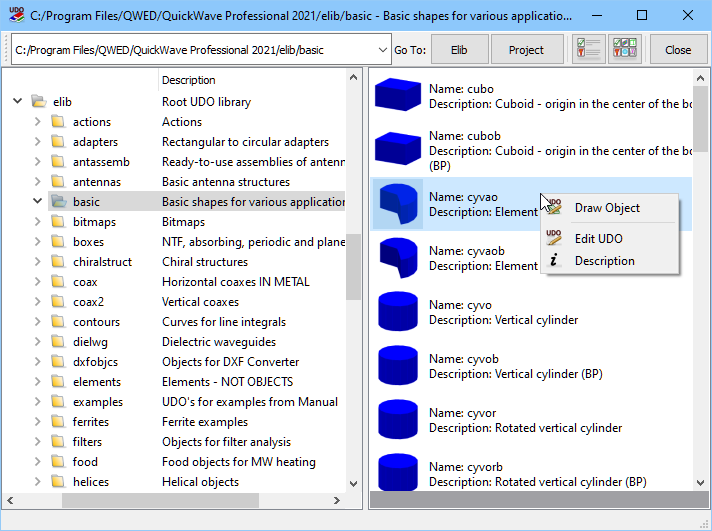
Fig. 2.8.1-2 Part of the header of the basic library.
The library header shows its contents. Each of the UDOs is represented by its name, a picture, and a short description. Left mouse button click over a chosen UDO opens its header as shown in Fig. 2.8.1‑3 (where cyvao.udo is used as an example), and allows the user to draw the object in QW‑Editor. Right mouse button click over a chosen UDO opens a menu with the following extended selection of commands:
· Draw Object – opens the UDO header as in the case of the left mouse button click over the UDO.
· Edit UDO – opens a UDO Editor and displays the UDO script to be analysed or modified.
· Description – opens a HTML with a detailed description of the considered UDO and explanation of all its parameters. Moreover, the description includes an example line for calling this UDO from other UDOs with the correct number of parameters. When we are writing a new UDO and wish to use an existing UDO as a nested object, we can copy the example CALL line into the new UDO, and further adjust its parameters to the locally used variables.
A majority of library UDOs are prepared in such a way that one UDO script produces one object. This is the most typical and usually most convenient way of working with UDOs, but not the only possible one. In particular, we can write a UDO script that defines a set of elements, but does not group these elements into one object. A number of such UDOs are available in the elib\elements subdirectory. They describe various transmission line ports and frequently used simple geometrical elements. They are supposed to be called (and modified) from within other UDO scripts written by the user.
Moreover, some UDOs (as for example cyvaob.udo) are marked as “biphased” or in short “BP”. They produce different QW-Editor images depending on QW-Editor phase at the time of their drawing. In the DRAFT phase the objects produced by biphased UDOs just signal roughly their shapes. They are not supposed to be used for exporting the mesh data to QW-Simulator. In the FINAL phase they provide the best approximation of the considered object, taking into account the assumed FDTD mesh. In this phase QW-Editor can generate the mesh and export data to QW-Simulator.
Normal application of the UDO libraries containing biphased objects consists of:
· drawing all the UDOs in DRAFT phase (activation command is available under ![]() button in Model tab of QW-Editor),
button in Model tab of QW-Editor),
· switching to FINAL phase (activation command is available under ![]() button in Model tab of QW-Editor),
button in Model tab of QW-Editor),
· using ![]() or
or ![]() button to export meshing and run QW-Simulator.
button to export meshing and run QW-Simulator.
If there are no biphased objects in use, all the operations should be performed in FINAL phase of QW-Editor. The philosophy behind biphased objects and their application will be presented in more detail in Application of biphased objects of this manual.
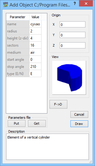
Fig. 2.8.1-3 Header of ct3r.udo.
Note that some of the library objects can be used as a standard (monophased) one or as a biphased one, depending on the value of one its parameters set in the header. One example is solid.udo in the library basic, which will be further discussed in Application of biphased objects.
For example, the object solid.udo in the library basic has a parameter named type, which sets the type of geometry approximation to be applied. More precisely, it defines mesh snapping properties of the object bottom and cover, similarly like we can snap the mesh to port plane, but with more possibilities:
· E - monophased object with E-planes enforced at the upper and lower limits of the solid block (E-plane is a plane within the FDTD mesh whereat the tangential E-field components are defined);
· N - monophased object with either E-planes or H-planes enforced at the upper and lower limits of the solid block (H-plane is a plane within the FDTD mesh whereat the tangential H-field components are defined),
· B - biphased object with the upper and lower limits of the solid block shifted to the closest E- or H-planes already existing in the FDTD mesh,
· B+ - biphased object with the upper and lower limits of the block shifted away from the block to the closest E- or H-planes already existing in the FDTD mesh, outside the object,
· B- - biphased object with the upper and lower limits of the block shifted into the block to the to the closest E- or H-planes already existing in the FDTD mesh, inside the object.
The above remarks also concern several other library objects, which use solid.udo for building up more complicated structures.