2.21.2 Viewing surface currents in an example project
In this section it has been described how to display surface current on metal walls of the ..\Various\Wgtocx\wgtocx1m1.pro project. Run the QW-Simulator and open the 2D/3D Fields Distribution window with the 3D Viewer display. Next, in the Components tab press ![]() button to show the surface current.
button to show the surface current.
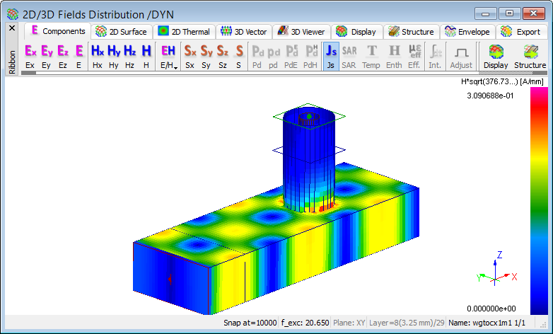
Fig. 2.21.2-1 The Js current on the metal walls in the wtocx1m1.pro.
3D Viewer Settings dialogue (see Fig. 2.21.2-2) allows changing the default settings concerning borders of viewed spaces and media used. When current flowing display, non-metal media visible on/off switching makes no difference of the picture.
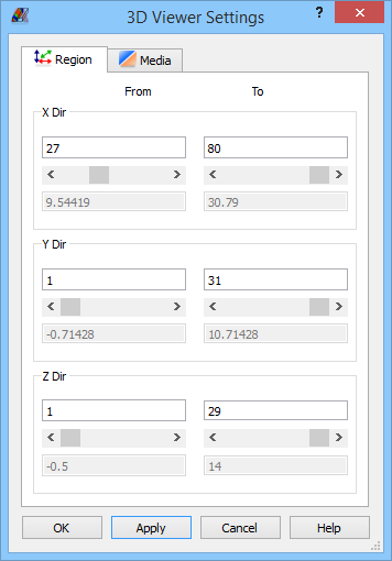

Fig. 2.21.2-2 The 3D Viewer Settings dialogue in the wgtocx1m1.pro.
The Region tab allows modification of viewed space borders – of current flowing here. Moving the slider along the structure one moves light grey plane showing the slider position (see Fig. 2.21.2‑3). The plane and cuboid edges limiting the structure are visible, until focus is changed in 3D Viewer Settings dialogue.
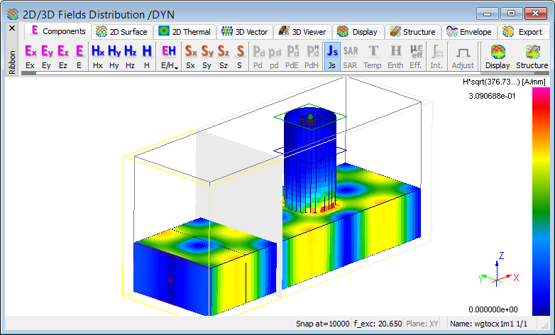
Fig. 2.21.2-3 The 3D Viewer display of 2D/3D Fields Distribution window in the wgtocx1m1.pro.
Changing from Component to Material in Depended Media column (see right Fig. 2.21.2‑4) allows observing materials cross sections.
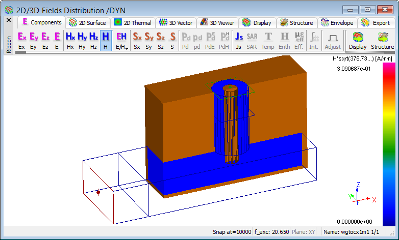
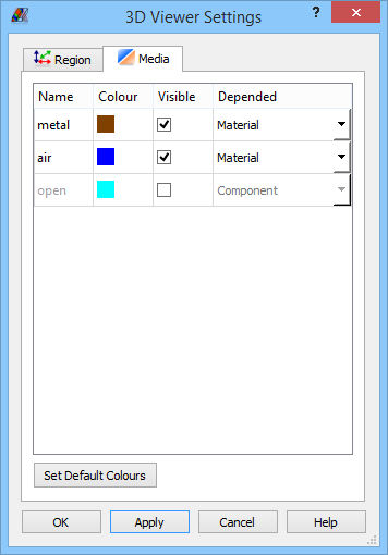
Fig. 2.21.2-4 The view selected materials cross sections on the 3D Viewer display in the wgtocx1m1.pro.