3.3 Drawing the structure
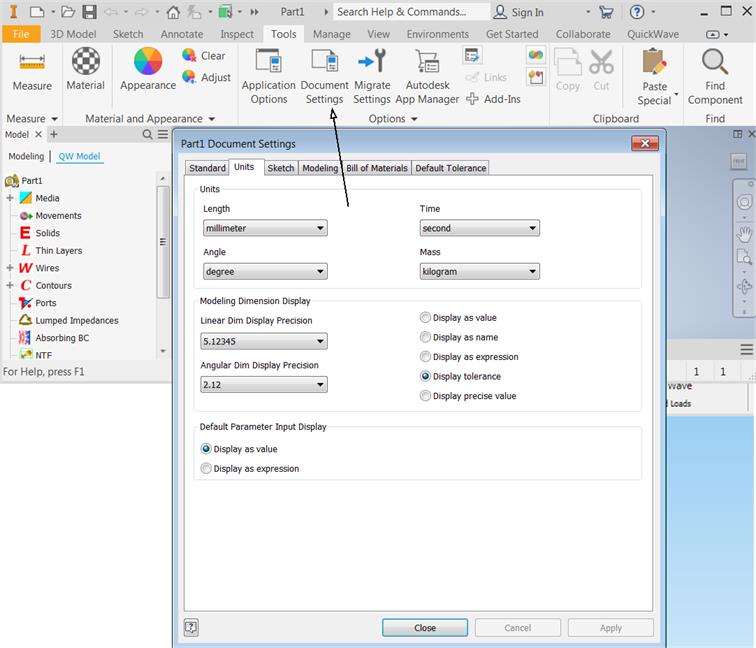
At this stage we will be creating the project geometry. First step that needs to be accomplished is choosing the units that will describe the geometry. To do that we go to Tools tab and from Units tab we choose millimeter.
The scheme of the waveguide to coaxial line transition and the dimensions are shown below. The centre of the coaxial line is placed 19.6 mm from the left edge of the waveguide.
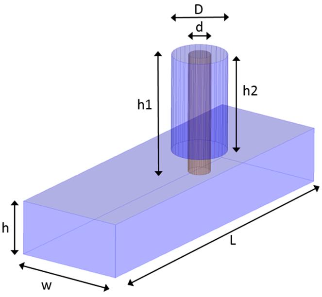
Waveguide to coaxial line transition scheme.
|
Parameter |
w |
h0 |
L |
d |
D |
h1 |
h2 |
|
Value [mm] |
10 |
5 |
30 |
2 |
5 |
11 |
9 |
It can be useful to place Parameters in the Inventor User Parameters section :
![]()
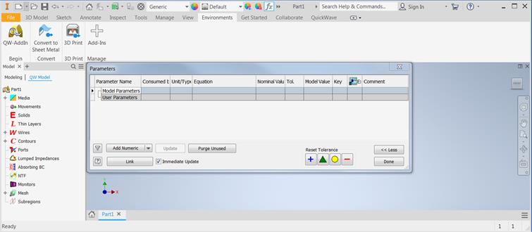
Initial state of the Inventor Parameters Window
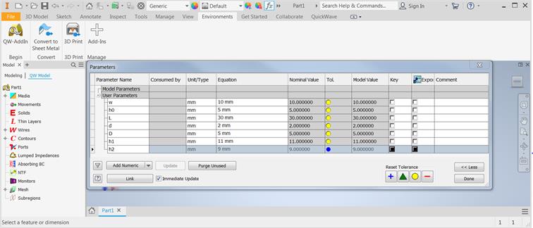
Model Parameters are introduced
To draw the structure we go to 3D Model tab. Let us start from drawing the air filled waveguide. As it was stated in Step 1, we need to draw only the inside of the structure (the surrounding medium is metal), thus we start from the air block, which stands for the waveguide inside. To draw the waveguide we press Extrude  button in the Create section and main planes appear.
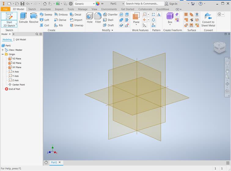
View after pressing Extrude button
Now Autodesk Inventor expects the user to choose plane on which the sketch of the waveguide bottom will be drawn. Please choose XY plane:
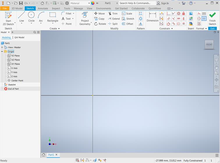
Autodesk Inventor in the 2D sketch mode on XY plane
Now, bottom of the waveguide can be drawn using Rectangle option. We can draw any rectangle with initial constrains.
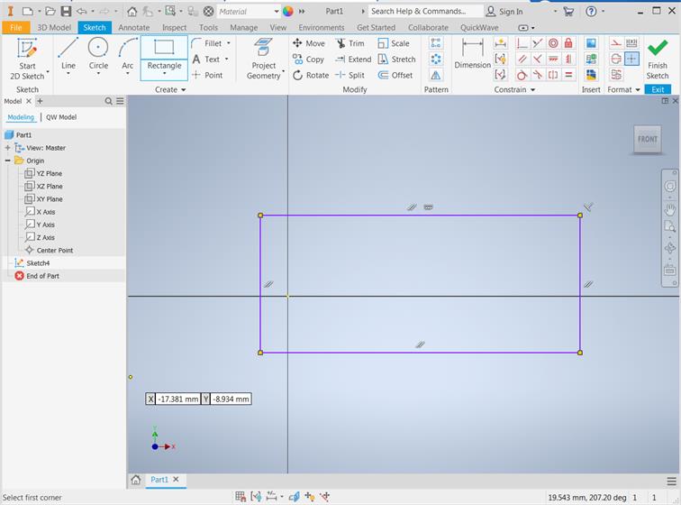
Rectangle sketch without user defined constraines
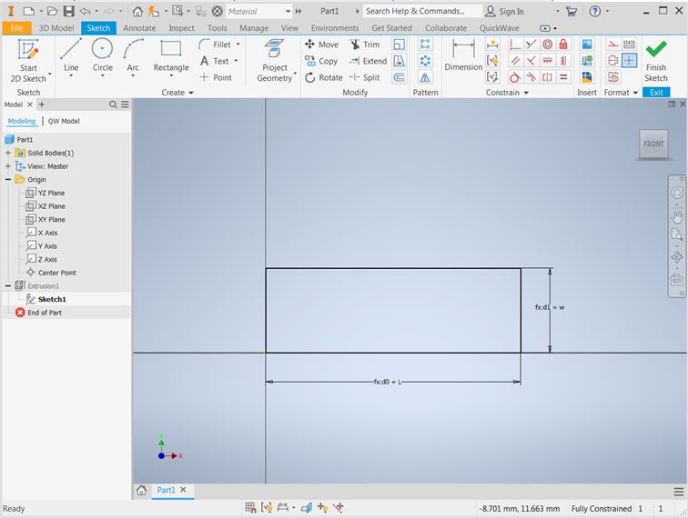
Rectangle sketch with constraines and dimensions
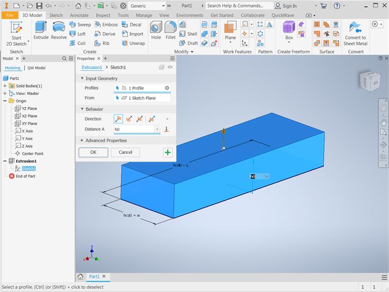
Rectangle sketch is extruded with the value h0
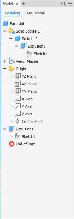
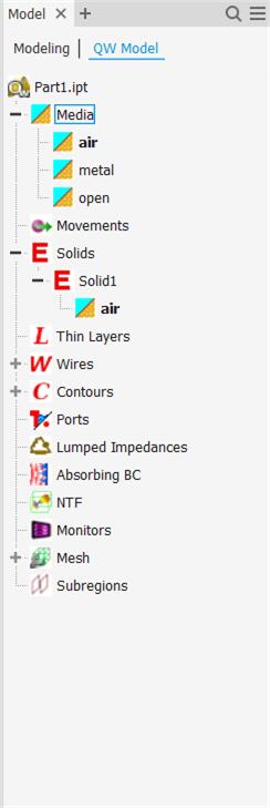
Autodesk Inventor and QW-Addin model tree window with waveguide object and default predefined name Solid1.
For better visualisation of the inside of the waveguide, we can change its transparency by standard Autodesk Inventor manner. It is also good to change name of the solid from Solid1 to waveguide and save project with wgtocx1.ipt name.
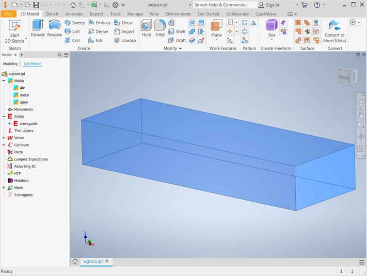
Waveguide solid with default medium air
In the next step we draw the inner and outer conductor of the coaxial line. To do that we can create new sketch on the top of the waveguide with two circles for inner conductor and air filling of the coaxial line.
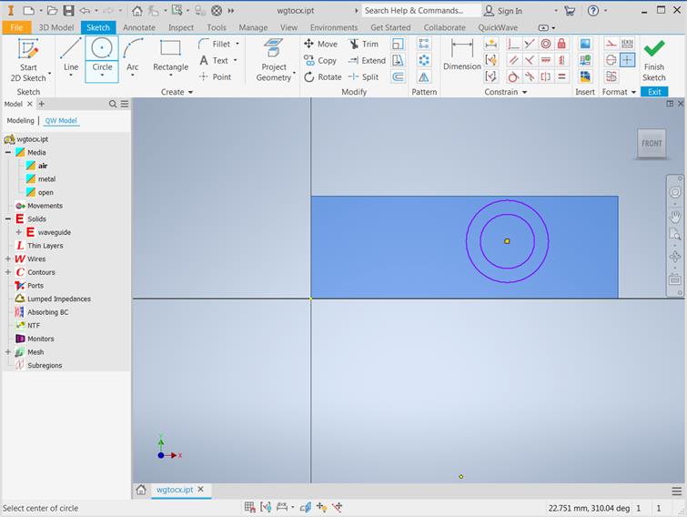
Sketch without user defined constraines
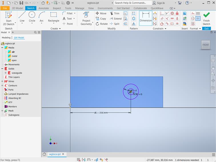
Sketch with user defined constraines and dimensions
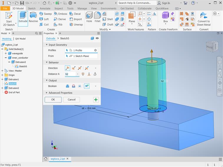
Now, we shall Extrude sketch to obtain inner conductor and air filling of the coaxial line.
![]()
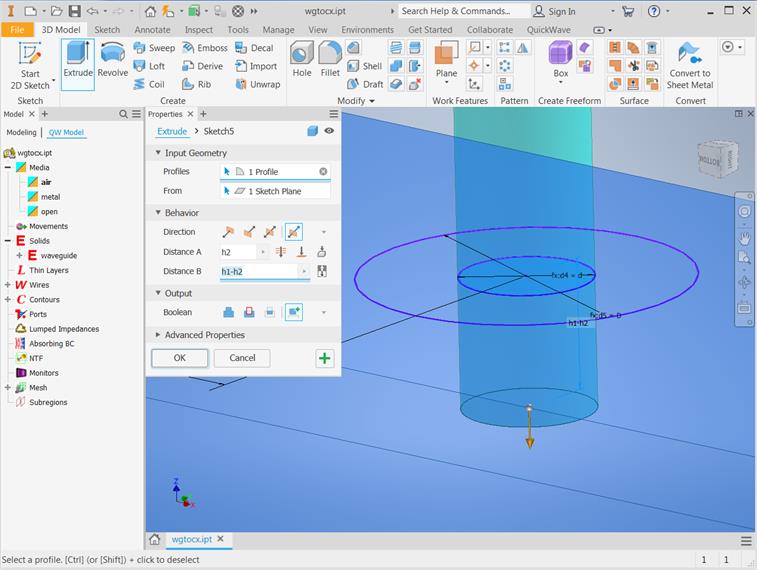
Extrussion of the inner conductor as New Solid
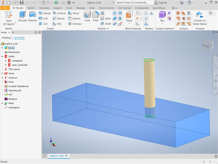
We name the object as inner_conductor and set its medium to metal. We assign its dimensions according to the above table and set its position to X= 19.6 mm, Y= 5 mm and Z= 3 mm. Those coordinates assure that the centre of the inner conductor is spaced from the left waveguide edge by a distance of 19.6 mm, is placed in the centre of waveguide width and is inserted into the waveguide for 2 mm. Now we can draw the air filling of the coaxial line.
Extrussion of the air filling of the coaxial line as New Solid (please be aware about Autodesk Inventor Sketch share)
We set the name to air_filling and choose the air medium for the object.
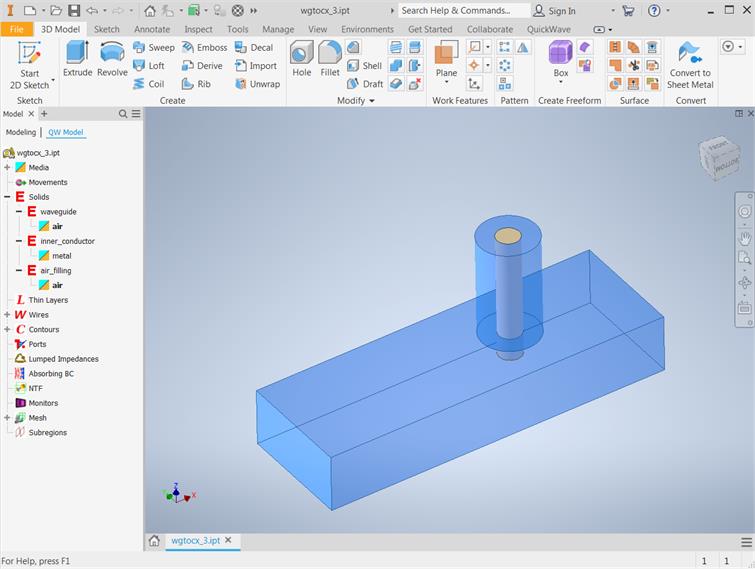
QW-Addin project window with waveguide to coaxial line transition.
Previous step: Defining the type of the structure.
Next step: Drawing the ports.