2.2.5 Wires
Any sketch 3D consisting of straight lines can be marked to be recognised as wire. Wire diameter can be smaller than mesh cell size. Such sketch shape will be approximated with the set of lines collinear with X, Y or Z axis.
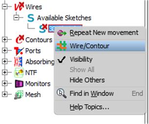
Fig.A 2.2.5-1 Available Sketch (Sketch 3D possible to be used as wire or contour) context menu.
Sketches 3D which can be converted to wires are listed under Available Sketches node in the Wires node (Fig.A 2.2.5-1). Pressing Wire/Contour command from the context menu of any of those sketches will mark the sketch to be recognised as wire from now on. Sketches marked as wires are listed directly under the Wires node. Running Wire/Contour command on the existing wire will remove it. The sketch it was based on will once again be available under Available Sketches node. Current version of the QW-AddIn supports only sketches containing line segments only.
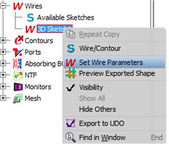
Fig.A 2.2.5-2 Wire context menu.
Each wire is described by its medium, diameter and resistance per length. Any of those parameters can be changed with the Set Wire Parameters command from the wire context menu (Fig.A 2.2.5-2). The Wire parameters dialogue will be opened (Fig.A 2.2.5-3). Only the PEC or Metallic medium can be assigned to wires. Wire diameter must be smaller than the mesh cell size.

Fig.A 2.2.5-3 Wire parameters dialogue.
Preview Exported Shape command shows how the shape defined by the wire will be approximated with line segments.