6.4 Patch Antenna Arrays
The Antenna Array tab options in 3D Radiation Pattern window are available only when the patch antenna array project is prepared with Patch Antenna Array module in QW-Modeller for QuickWave.
Patch Antenna Array module in QW-Modeller for QuickWave.
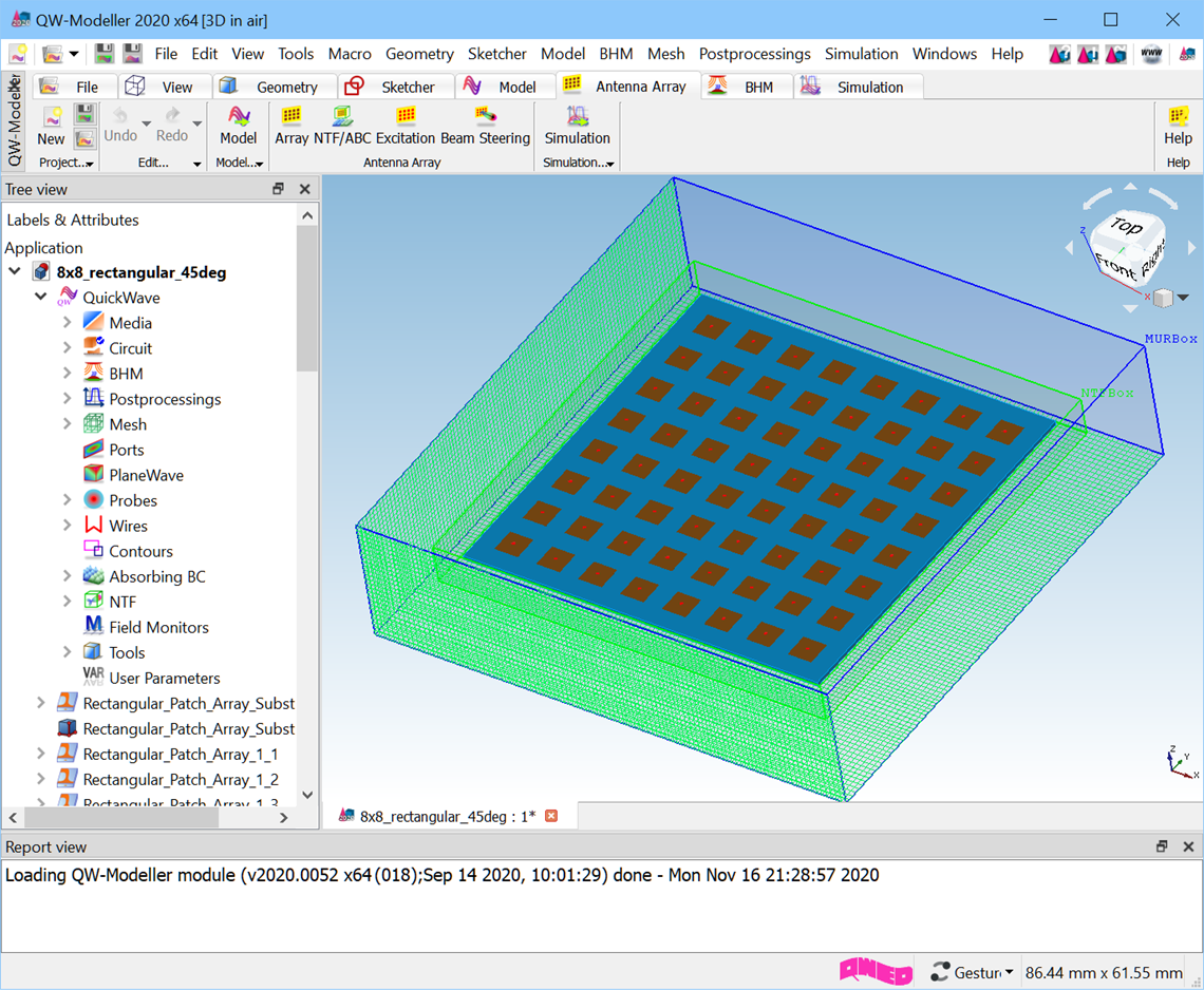
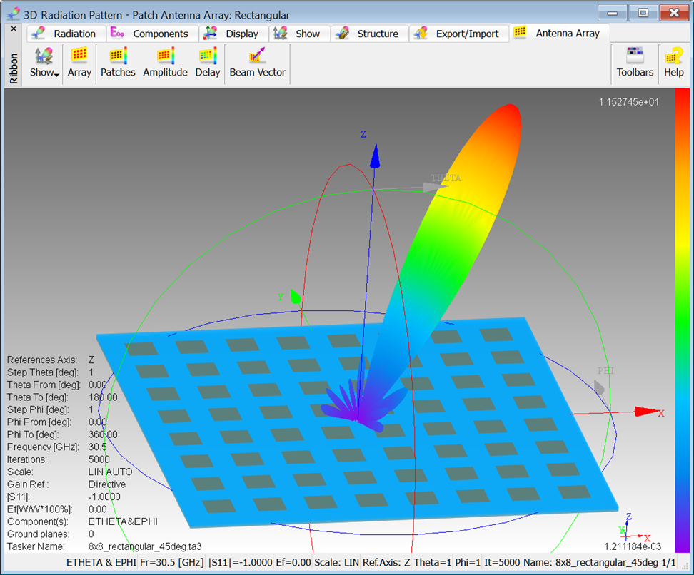
8x8 rectangular patch antenna array in QW-Modeller for QuickWave.
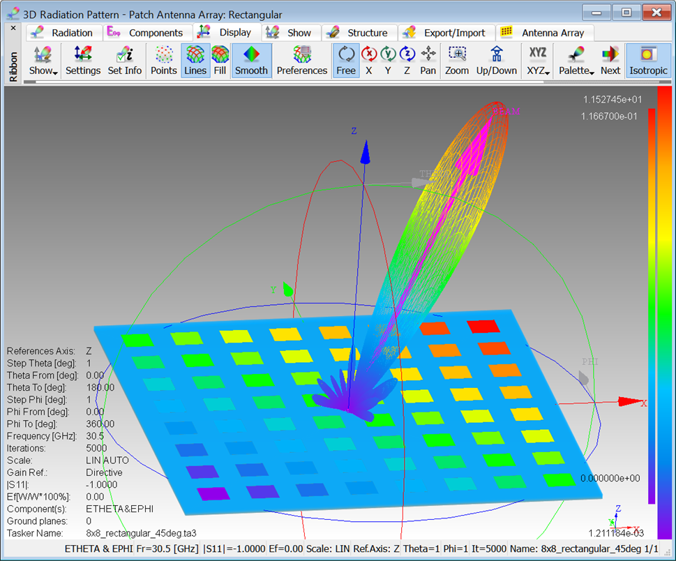
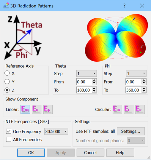
The 3D radiation pattern will be calculated for the parameters (angles’ range, etc.), which can be set in the 3D Radiation Patterns dialogue.
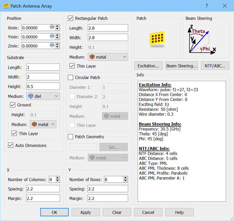
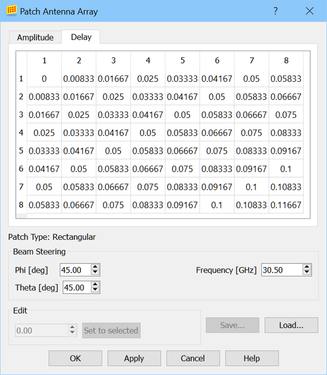
The excitation parameters (amplitude and delay) for patch antenna array can be observed in the Patch Antenna Array dialogue.
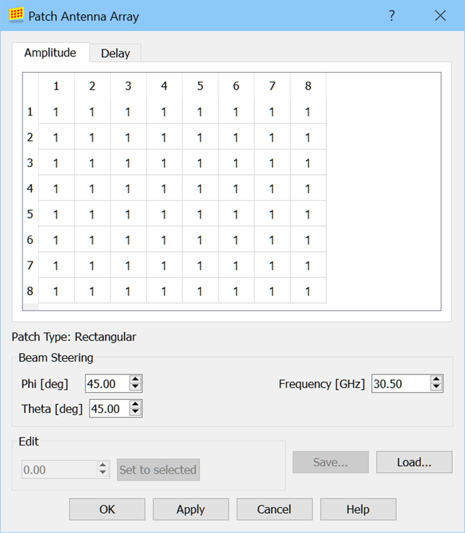
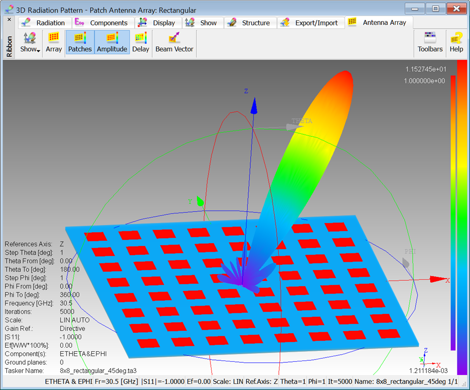
The ![]() button in Antenna Array tab allows for checking the distribution of excitation amplitude across the array (for each excitation point).
button in Antenna Array tab allows for checking the distribution of excitation amplitude across the array (for each excitation point).
The ![]() button in Antenna Array tab allows for checking the distribution of excitation delay (corresponding to phase shift) across the array (for each excitation point).
button in Antenna Array tab allows for checking the distribution of excitation delay (corresponding to phase shift) across the array (for each excitation point).
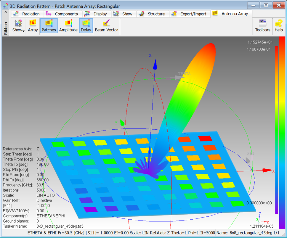
When the amplitude or delay distribution is displayed, the second colour bar, for visualisation of the colour palette and value range (from minimum to maximum) of the two parameters, appears on right side of the display.
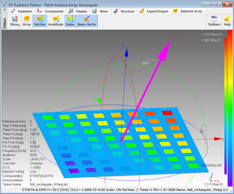
The ![]() button in Antenna Array tab allows for observing a vector indicating direction of main radiation beam as specified in the Patch Antenna Array module in QW-Modeller for QuickWave.
button in Antenna Array tab allows for observing a vector indicating direction of main radiation beam as specified in the Patch Antenna Array module in QW-Modeller for QuickWave.