4.12.5 Example
In this chapter typical test example of the F3DPost usage will be described.
The example project was created using QuickWave Modeller 2017.
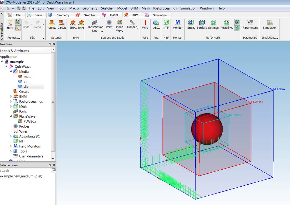
On the picture we see the red sphere created with “diel” material which permittivity can be changed in wide scope. Sphere is surrounded by absorbed boundary condition (MURbox - blue) and plane wave box (PLWbox - red). The most inner box (MeshBox - cyan) is intentionally applied to fulfill important condition for F3DPost of fixing cells size in the project after changing materials of some elements inside the simulation volume. In other QuickWave CAD’s like QuickWave editor or QuickWave Addin for Autodesk Inventor user should use corresponding method to MeshBox to fix mesh between scenarios version to have possibilities to apply Field 3D Post Processing.
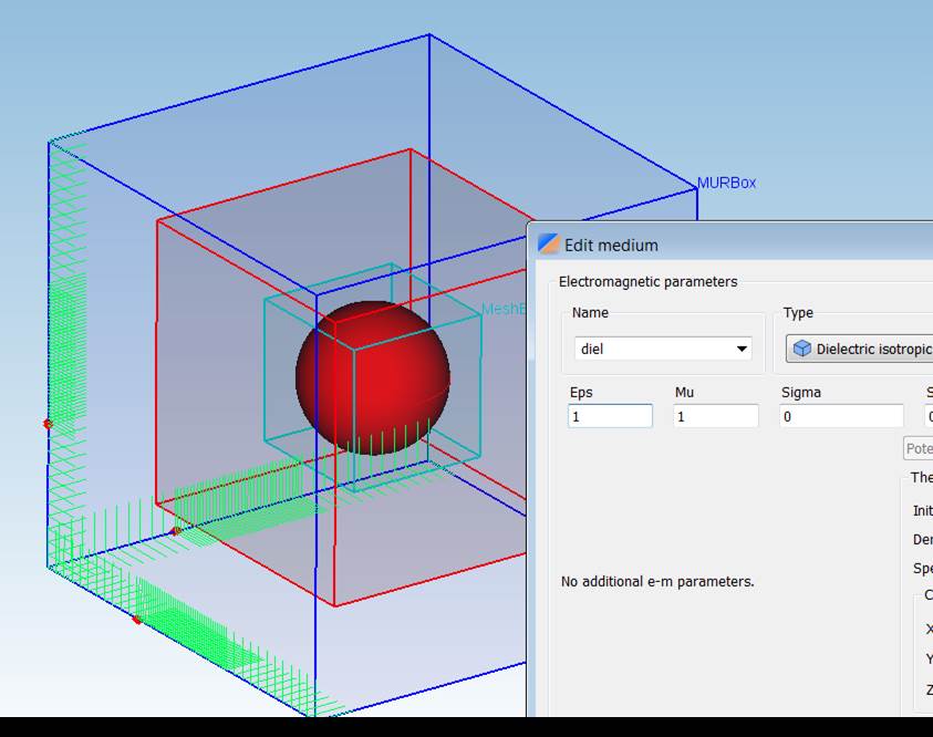
On the picture below mesh is fixed and denser in the sphere region just to have possibility to change permittivity (Eps), permeability (Mu) or other material parameters of the sphere in the scenario variants and more than 10 cells per wavelength FDTD typical condition was fulfilled.
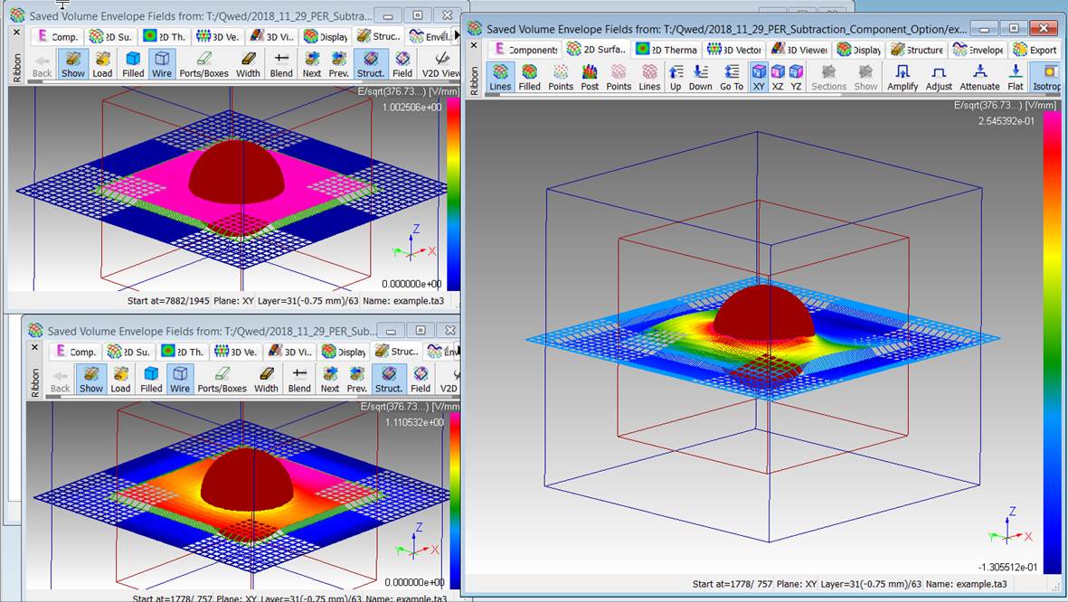
On the subsequent picture subtracted option was applied for above scenario and volume envelope calculation for sphere with material air (upper left window), and with dielectric εr=2 (relative permittivity) (lower left window) and subtracted envelope Ez field (*.ve3) on the right.