9.4 Model Input
All the necessary input data for QW-FFM are defined through the *.ff3 file.
The data format is explained below based on examplary *.ff3 file
…\qw_examp\QW_3D\BHM\Heat_FluidFlow\ pp_X_.ff3
! Quick Wave Fluid Flow Modules ver. 1.0
! type of modules 3D
! FFM_VELOCITY_X save every step 50
! FFM_VELOCITY_Y save every step 50
! FFM_VELOCITY_Z save every step 50
! FFM_PRESSURE save every step 50
! number of modules 2
**********************************************
! medium fluid
! volume/limits (xmin,xmax,ymin,ymax,zmin,zmax) -22.715 -11.825 -75. 75. 0. 10.
! inflow/pressure[Pa]/limits 0.5 -22.715 -11.825 -75. -75. 0. 10.
! inflow/temperature[degC] 27
! outflow/pressure[Pa]/limits 0.0 -22.715 -11.825 75 75 0. 10.
! wall/type/limits NOSLIP -22.715 -22.715 -75 75 0. 10.
! wall/type/limits FREESLIP -11.825 -11.825 -75 75 0. 10.
! wall/type/limits FREESLIP -22.715 -11.825 -75 75 0. 0.
! wall/type/limits FREESLIP -22.715 -11.825 -75 75 10. 10.
**********************************************
! medium fluid
! volume/limits (xmin,xmax,ymin,ymax,zmin,zmax) 11.825 22.715 -75. 75. 0. 10.
! inflow/pressure[Pa]/limits 0.5 11.825 22.715 -75. -75. 0. 10.
! inflow/temperature[degC] 27
! outflow/pressure[Pa]/limits 0.0 11.825 22.715 75 75 0. 10.
! wall/type/limits NOSLIP 22.715 22.715 -75 75 0. 10.
! wall/type/limits FREESLIP 11.825 11.825 -75 75 0. 10.
! wall/type/limits FREESLIP 11.825 22.715 -75 75 0. 0.
! wall/type/limits FREESLIP 11.825 22.715 -75 75 10. 10.
**
Format description:
1. The first line is a header.
2. Next line defines type of module:
! type of modules 3D
3D is a default setting. The optional type can be2D – in such case the equations will not consider the Z-dir elements.
3. The following four lines are not mandatory. If applied, they determine how often (frequency expressed in FFM steps) values of velocities vx, vy, vz and pressure p (FFM_VELOCITY_X, FFM_VELOCITY_Y, FFM_VELOCITY_Z and FFM_PRESSURE) will be saved to volume instantaneous *.vi3 file. The line ended with “0” means no saving of specific variable.
! FFM_VELOCITY_Y save every step 50
4. The next line indicates number of fluid media (modules) considered in the simulation project.
! number of modules 2
Each fluid module is then defined in the following lines according to the below description:
a. The name of the medium
! medium fluid
b. The box limits of the fluid (boundary coordinates of the area occupied by the medium)
! volume/limits (xmin,xmax,ymin,ymax,zmin,zmax) valxmin valxmax, valymin, valymax, valzmin, valzmax
c. The pressure and the wall limits of the inflow
! inflow/pressure[Pa]/limits 0.5 -22.715 -11.825 -75. -75. 0. 10.
d. The temperature of the inflow
! inflow/temperature[degC] 27
e. The pressure and the wall limits of the outflow
! outflow/pressure[Pa]/limits 0.0 -22.715 -11.825 75 75 0. 10.
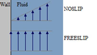
f. The type (boundary conditions) and the limits of the wall
! wall/type/limits NOSLIP -22.715 -22.715 -75 75 0. 10.
The key word of the type can be NOSLIP or FREESLIP, and a illustration of the corresponding velocity behaviour is shown below.