9.2 The Philosophy of the QW-Fluid Flow Module
The internal Fluid Flow Module is integrated with internal Heat Flow Module of the QW-BHM it the QW-Simulator.
The list presented below indicates the following steps performed by BHM working with the internal QW-FFM regime:
1. The FDTD analysis with sinusoidal excitation is run until the electromagnetic steady-state is reached.
2. The 3D pattern of average dissipated power P(x,y,z) is created.
3. The enthalpy (or rather enthalpy density) distribution is updated.
4. Current field values (enthalpy density field, dissipated power field, and temperature) are sent internally to the QW-HFM module.
5. Internal QW-FFM and QW-HFM module perform computations on the received data:
a. The single-phase of the flow regime begins from solving Poisson's equation using iterative method.
b. The calculated pressure is an input for theNavier-Stokes equations.
c. The calculated velocities (N-S equations) are the input for the energy conservation equations for enthalpy calculation.
d. The enthalpy distribution is calculated in QW-FFM (without accounting for heat transfer).
e. The temperature distribution is updated in QW-FFM.
f. The single-phase of Heat Flow Module is called.
g. The temperature in each FDTD cell is updated.
The steps from a. to g. are repeated until all internal QW-HFM steps (determined by HFM stability criterion) are completed.
6. The temperature distribution in each FDTD cell is updated.
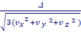
For accurate and converged results, the internal time of the Fluid Flow Module τ obeys the stability conditions:
τ <=
τ <=![]()
where ![]() is a min size of cells
is a min size of cells