10.2 Coaxial waveguide with heat flow module and boundary conditions
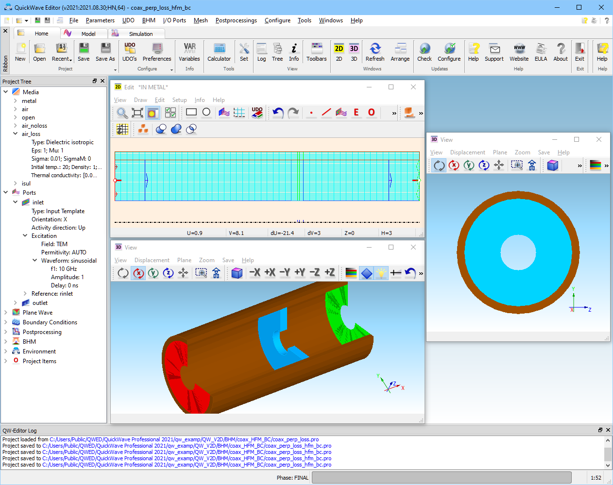
This example is available in .../QW_V2D/BHM/coax_HFM_BC/coax_perp_loss_hfm_bc.pro in the QuickWave examples directory.
General Description
Circular waveguide with lossy load showing microwave heating and heat transfer effects (BHM and Heat Flow modes).
Temperature dependent material parameters for medium air_loss are defined in the air_loss.pmo file:
# airloss composite media file for QW-BHM module
# DATA FROM 300.15 K to 1300.15 K
!Temperature Enthalpy EPa SIGa SpecHeat Density Ka
# C J/cm3 S/m J/gC g/cm^3 W/cmC
20. 0.0 1. 0.01000 1.00 1. 0.001
120. 100. 1. 0.01000 1.00 1. 0.001
The boundary condition definition files (*.pm2) let the user provide all the necessary information on boundaries to the QW-HFM module without the need to manually select all the walls and define their thermal properties. Walls without explicitly defined boundary conditions will be treated as boundaries with default conditions. The default boundary condition can be chosen by the user by modifying the DefaultBC option in the Preferences dialogue of QW-Simulator or in the initialisation file.
The boundary condition definition file contains the Enthalpy and Temperature columns known already. Additional column Ha containing the values of the convective heat transfer coefficient (the unit is Wcm-2K-1) defined as a function of temperature and/or enthalpy. The heat transfer coefficient can assume values ranging from 0 (adiabatic boundary condition) to very large, tending to +INF (explicit boundary condition).
There are four boundary condition definition files defined for this project (air_noloss_air_loss.pm2, isul_air_loss.pm2, metal_air_loss.pm2, metal_isul.pm2) and are used during simulation..
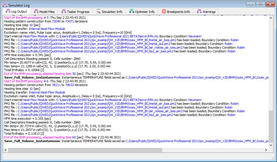
Log Output tab of the Simulator Log window showing details of coax_perp_loss_hfm_bc.pro example execution stages.
Temperature Distribution
|
BHM iteration |
Min temp oC |
Max temp oC |
|
1 |
20.11 |
20.31 |
|
2 |
20.28 |
20.55 |
|
3 |
20.35 |
20.76 |
|
4 |
20.48 |
20.95 |
|
5 |
20.61 |
21.13 |
|
6 |
20.73 |
21.30 |
Temperature evolution in coax_perp_loss_hfm_bc.pro.
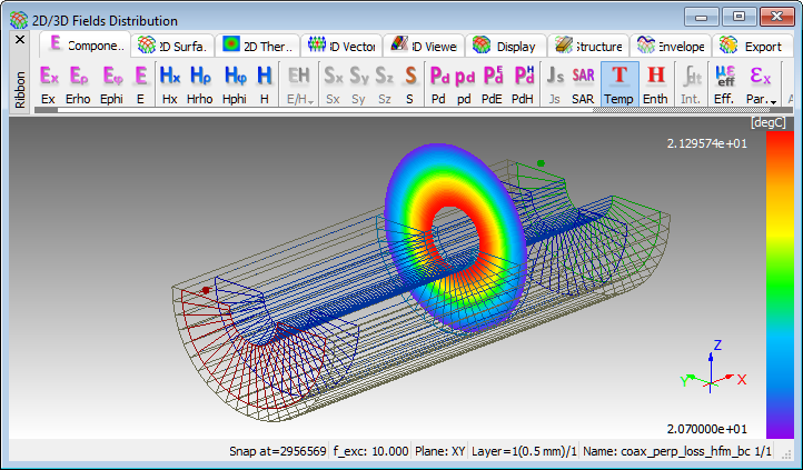
Final temperature pattern across the load.
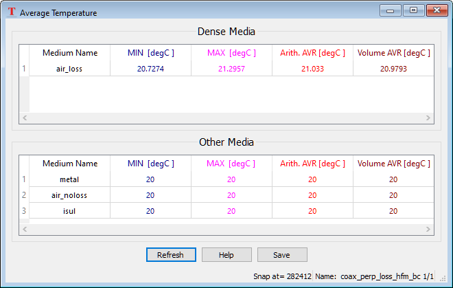
The Average Temperature window presents the values of average temperature in dense media and non-dense media.
Enthalpy Distribution
|
BHM iteration |
Total enthalpy J |
|
1 |
0.0219 |
|
2 |
0.0429 |
|
3 |
0.0631 |
|
4 |
0.0823 |
|
5 |
0.1007 |
|
6 |
0.1181 |
Total enthalpy evolution in coax_perp_loss_hfm_bc.pro.
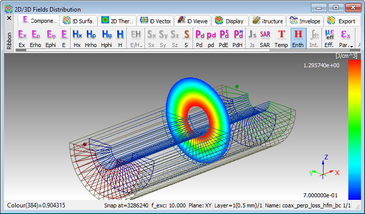
Final enthalpy pattern across the load.
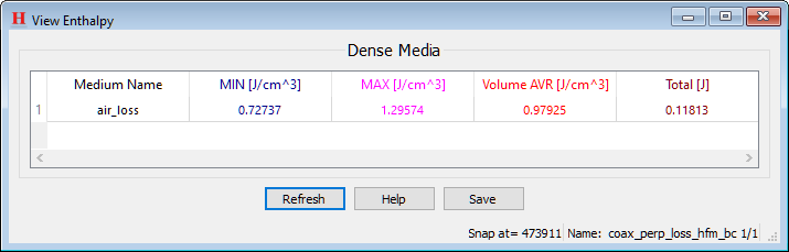
The View Temperature window presents the values of average and total enthalpy in dense media.