7 Optimisation of axisymmetrical corrugated horn antenna
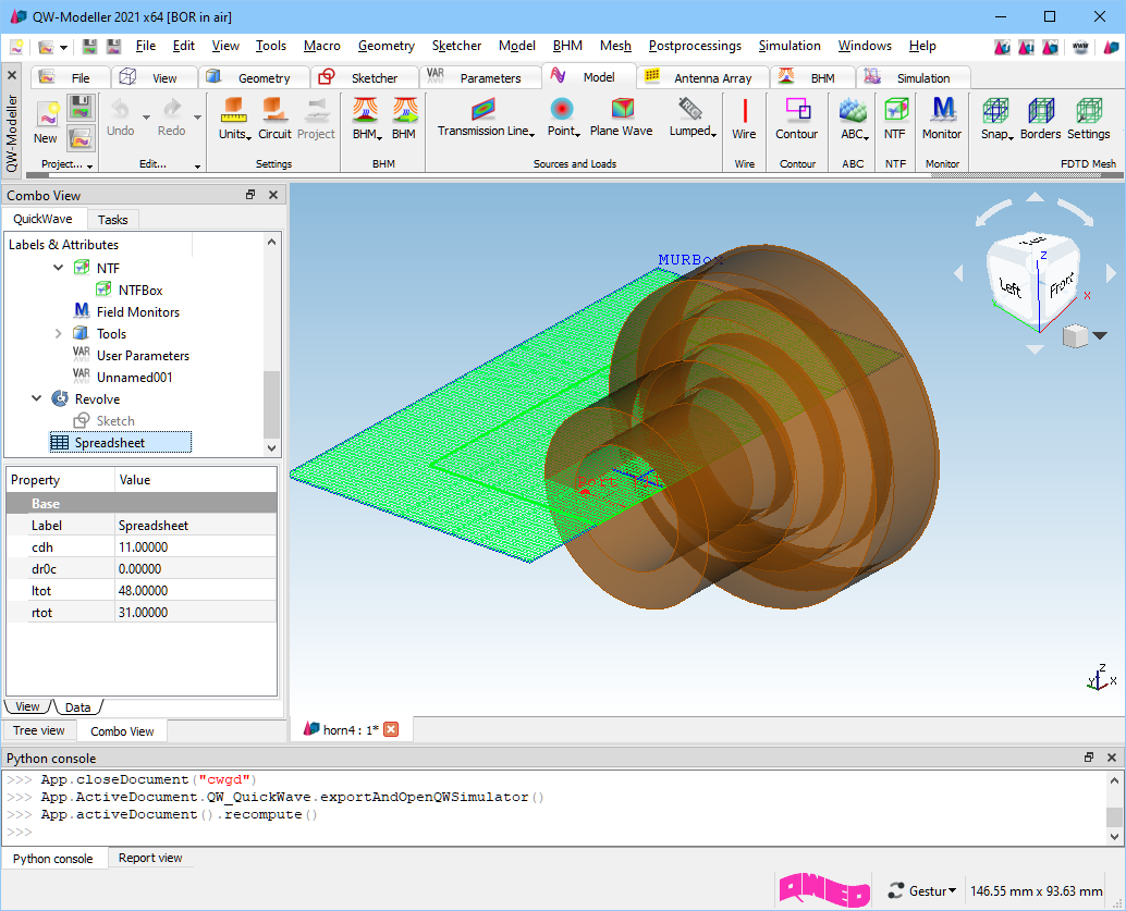
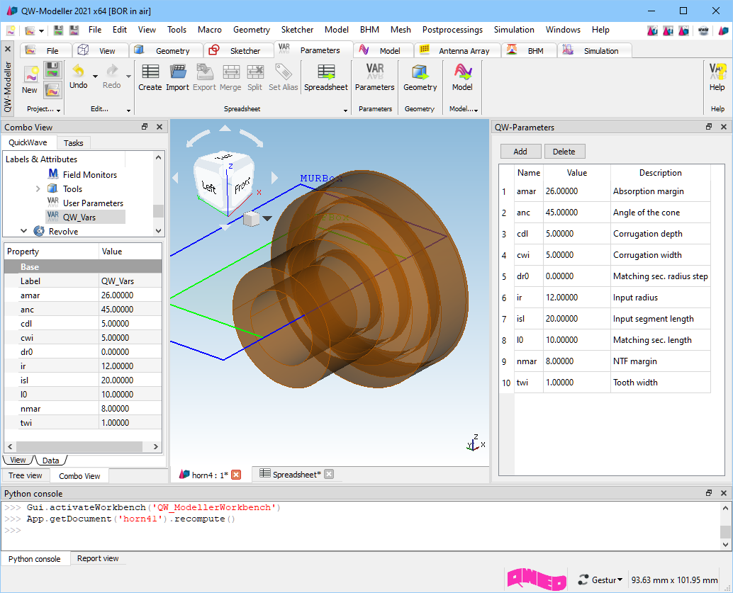
The present example considers an axisymmetrical corrugated horn antenna. This example is available in .../QW-V2D/Opt_plus/Horn4/horn4.QWPro in the QW-Modeller examples directory and can be loaded using File®Open Examples... command from main menu.
Axisymmetrical corrugated horn project in QW-Modeller.
The meshing has been generated with the help of AMIGO assuming 25 cells per wavelength at the uppermost frequency of 14 GHz.
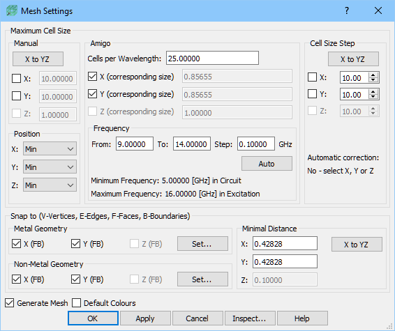
Meshing in horn4 example.
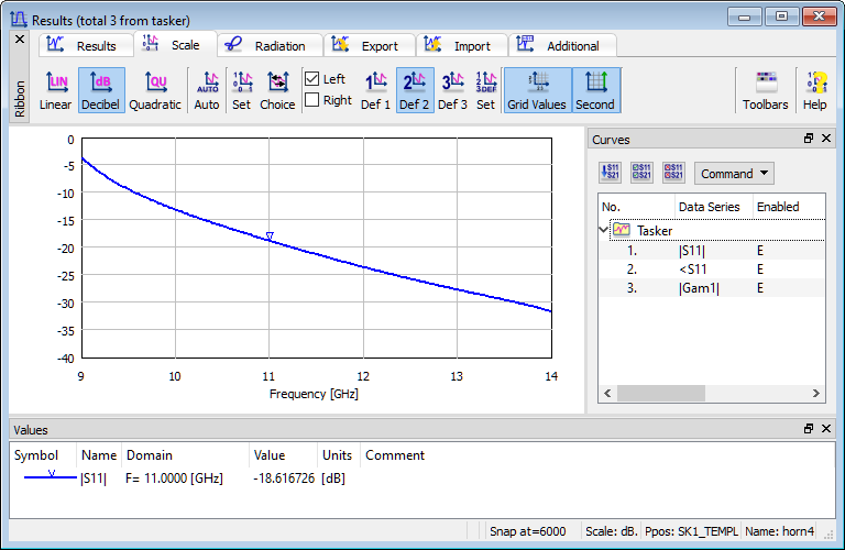
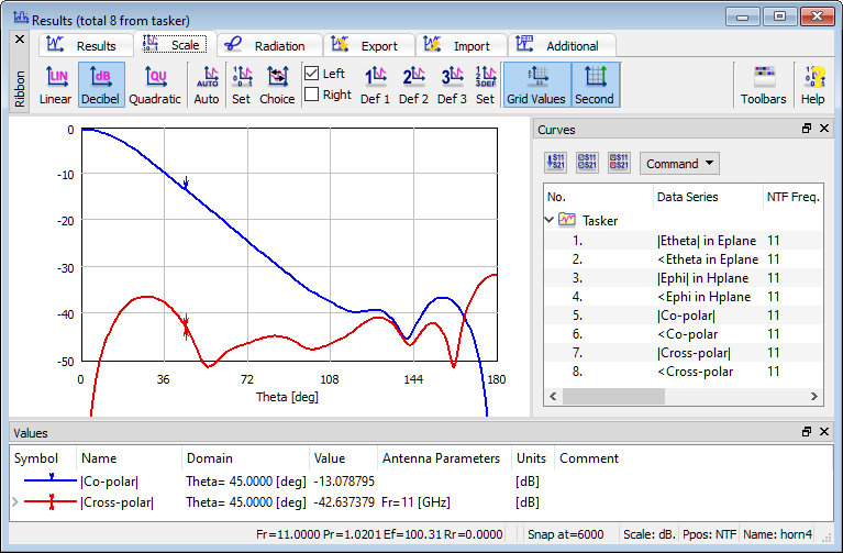
Reflection coefficient and radiation patterns of horn4 example.
The antenna parameters are relatively good but we may wish to improve them with respect to particular criteria. Assume the following requirements:
- reflections in the band between 10.5 and 11.5 GHz at the level of 0.05 (-26 dB) or better,
- main beam width at 11 GHz measured at the level of 0.316 (-10 dB) equal to ± 45º,
- cross-polar at 11 GHz, in the entire range of angles, lower than 0.05 (-26 dB).
It can be seen that only the last of the three requirements is fulfilled by the original design.
![]() button from Parameters tab opens QW-Parameters dock window with already defined user variables which can be used for parametrisation of antenna structure.
button from Parameters tab opens QW-Parameters dock window with already defined user variables which can be used for parametrisation of antenna structure.
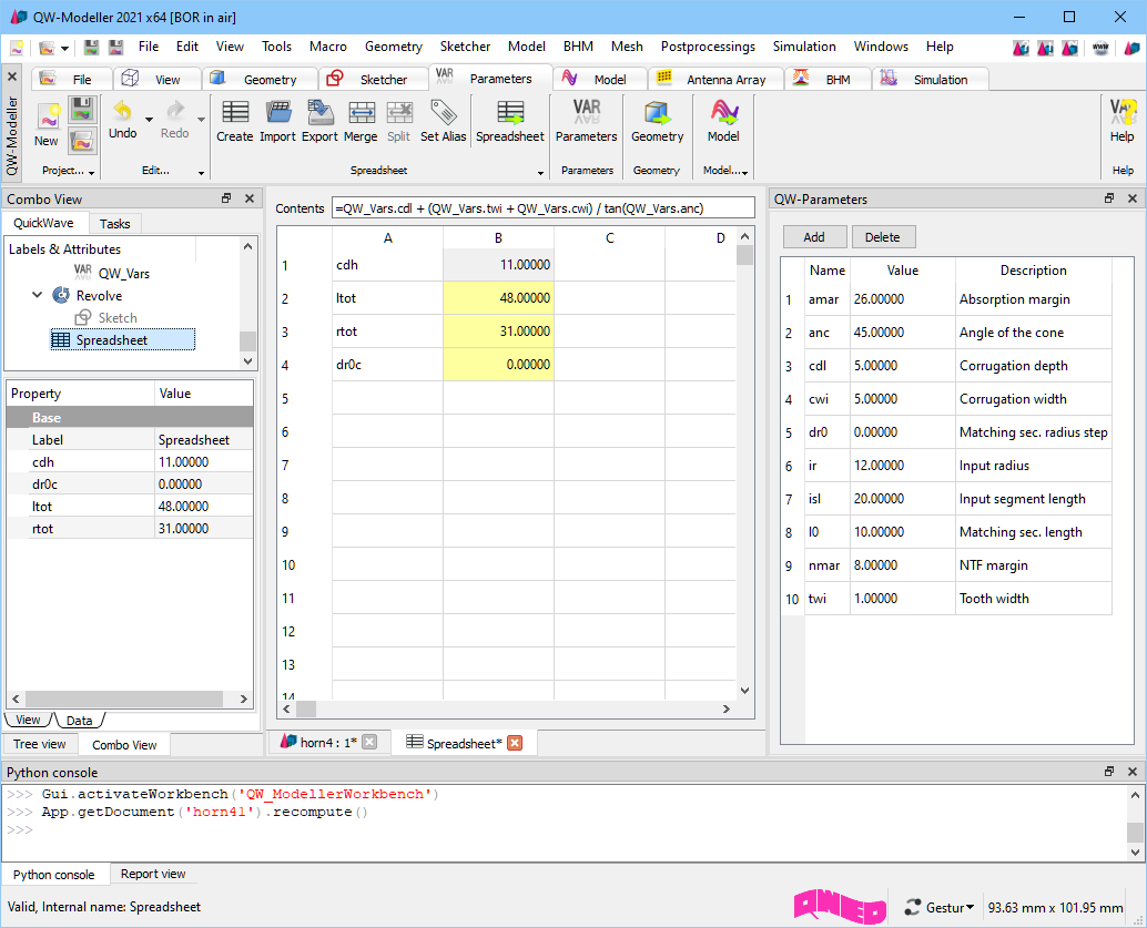
The Spreadsheet object allows defining additional variables which can be combinations of already defined user variables in QW-Parameters dock window. These variables will be used in optimisation.
The final antenna is obtained after revolving the base antenna sketch. The sketch is fully constrained and constraints marked with ![]() are parametrised.
are parametrised.
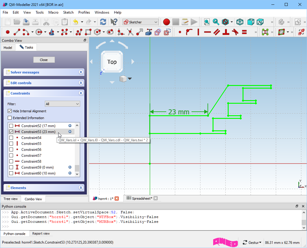
By double-clicking on selected constraint the dialogue for introducing the value will open. The black value and ![]() icon means that the constrain is defined by value. The black value and
icon means that the constrain is defined by value. The black value and ![]() icon means that the constraint is parametrised.
icon means that the constraint is parametrised.

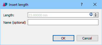
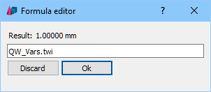
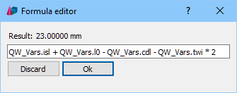
Clicking ![]() or
or ![]() icon the Formula editor dialogue will appear and we can define the variable or formula that will be used.
icon the Formula editor dialogue will appear and we can define the variable or formula that will be used.
Now press ![]() to export the project and open QW-Simulator. In QW-Simulator we open Configure Optimiser (
to export the project and open QW-Simulator. In QW-Simulator we open Configure Optimiser (![]() button). Four objectives have been defined according to the requirements presented earlier in this Section:
button). Four objectives have been defined according to the requirements presented earlier in this Section:
- |S11| in the band of 10.5 to 11.5 GHz is supposed to be as low as possible but any value below 0.05 is acceptable (Upper field). This means that when the maximum value of |S11| in the considered band equals to |S11|max, it will generate the value of the goal function for this objective equal to (|S11|max -0.05)/0.05.
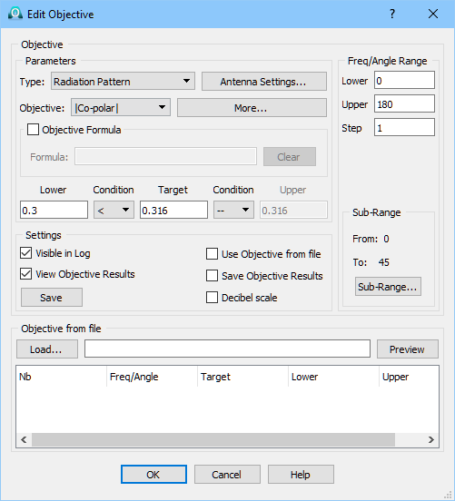
- The Co-polar relative gain in the range of angles between 0º and 45º should be higher than 0.3 and the goal function for this objective will be calculated as (0.3-|Co-polar|min)/(0.316-0.3).
- The Co-polar relative gain in the range of angles between 45ºand 180º should be smaller than 0.33 and the goal function for this objective will be calculated as (|Co-polar|max-0.33)/(0.33-0.316).
- The Cross-polar relative gain in the range of angles between 0º and 180º should be smaller than 0.05, and the goal function for this objective will be calculated as (|Cross-polar|max-0.05)/0.05.
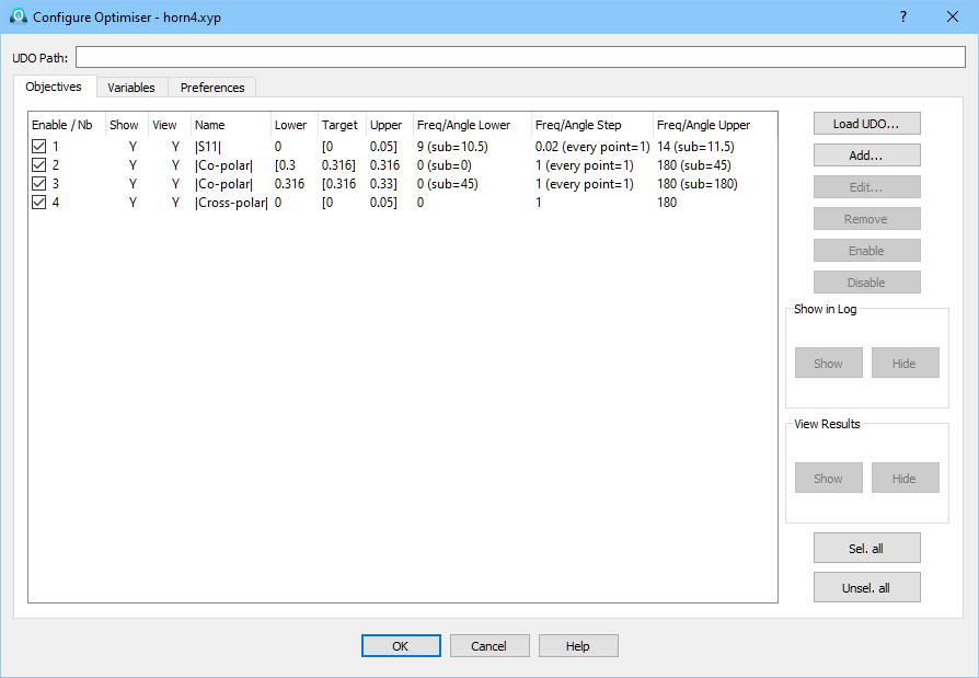
During the optimisation the highest value of the goal functions for individual objectives will be taken as the value of the overall goal function.
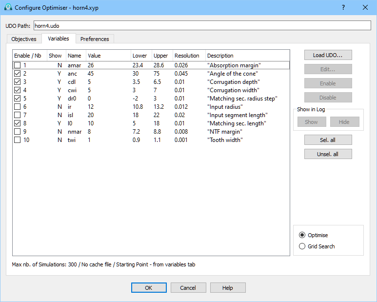
The variables that will be use in optimisation are defined in the QW-Parameters dock window in QW-Modeller.
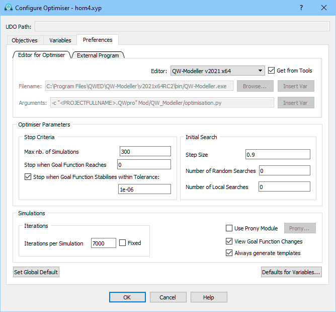
The Preferences tab defined in the Configure Optimiser dialogue. In the upper part we have a set of parameters for communication of QW-OptimiserPlus with other programs. Normally, the user does not need to change them and can rely on default settings. Advanced users may refer to QW-OptimiserPlus manual for more information. The user needs to set proper values only in two sections of the Preferences tab: Simulations and Stop criteria.
In Simulations we need to specify how many FDTD iterations will be performed during each run of QW-Simulator. This should be based on the user’s experience with a single run of the considered project. When running horn4.QWPro we can see that the S-parameter results stabilise after about 5000 iterations. With some additional margin we have put 7000 into the QW‑OptimiserPlus Preferences.
In Stop Criteria we have set 300 as the maximum number of simulations performed and 0 as the level of the goal function, which terminates the optimisation. Level 0 means that all the Objectives have been reached. Sometimes the goal function stabilises at a certain minimum level above 0. In such a case, we know that this is a local minimum of the goal function but cannot be sure that other lower minimum does not exist. If the box: Stop when Goal Function Stabilises within Tolerance is checked, the optimising process will stop at the reached local minimum. Otherwise QW‑OptimiserPlus will try to jump out of that minimum in a search for other minima. It may succeed although there is no guarantee that it will. In the latter case, the process will stop on Maximum Number of Simulations Performed. We should also choose proper QW-Modeller as an project Editor.
Start the optimisation by pressing ![]() button in Optimiser tab. QW-Simulator opens six windows: Simulation Log, Results window forS11, two Results windows for 2D radiation pattern results for Co-planar (with the same results of simulation but marking different targets and bounds of the two objective), Results window for 2D radiation pattern for Cross-planar and Goal Function Results window. After 13 runs of QW-Simulator, QW-OptimiserPlus stops and informs: Target objective function value reached). We can also see the optimal set of variables. The best run (number 13) is marked by an asterisk in the Simulation Log.
button in Optimiser tab. QW-Simulator opens six windows: Simulation Log, Results window forS11, two Results windows for 2D radiation pattern results for Co-planar (with the same results of simulation but marking different targets and bounds of the two objective), Results window for 2D radiation pattern for Cross-planar and Goal Function Results window. After 13 runs of QW-Simulator, QW-OptimiserPlus stops and informs: Target objective function value reached). We can also see the optimal set of variables. The best run (number 13) is marked by an asterisk in the Simulation Log.
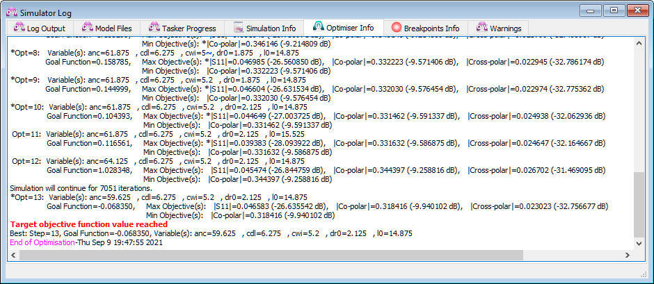
Fragment of the Simulator Log window generated during optimisation of horn4 example.
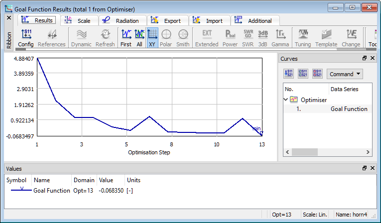
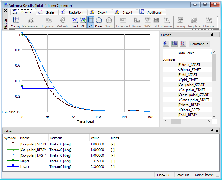
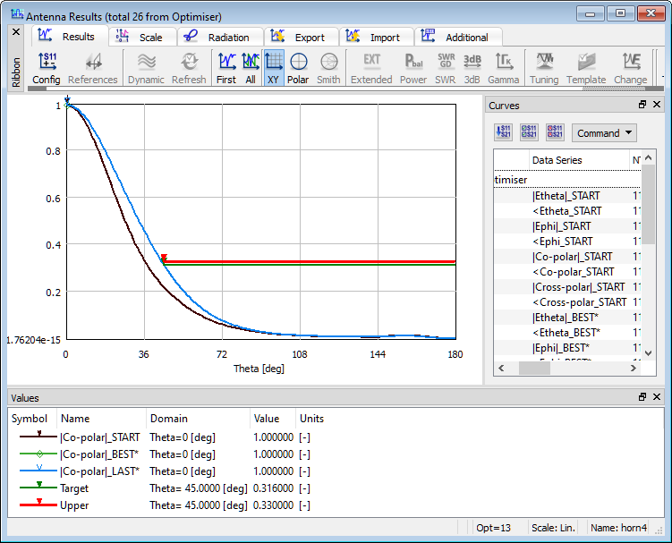
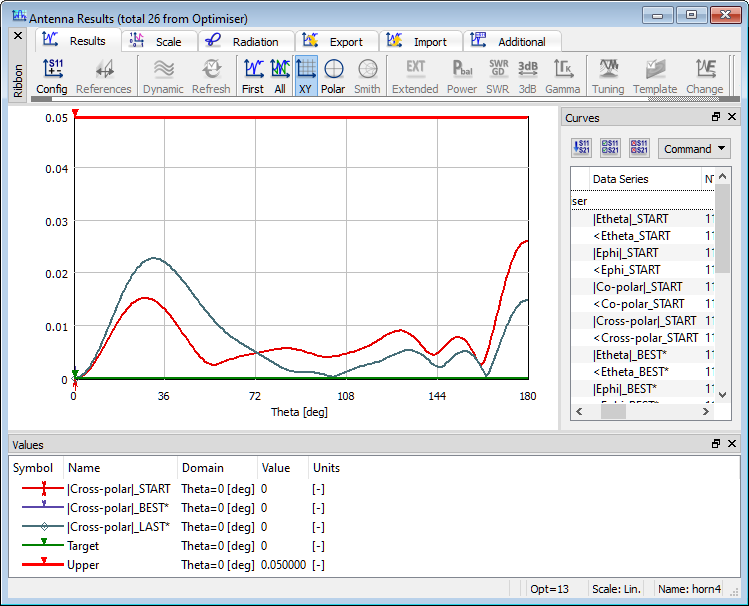
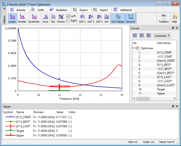
Results of optimisation of horn4 example.
The display of simulation results for the Start, Best and Last run in the optimisation process as well as the evolution of the Goal Function. It can be noted that the minimum of |S11| has moved to the requested frequency 11 GHz. The width of the main beam has been adapted to the requirements. The crosspolar characteristic is slightly worse than at the starting point but it meets the requirements anyway.