18.8 Setting up the mesh
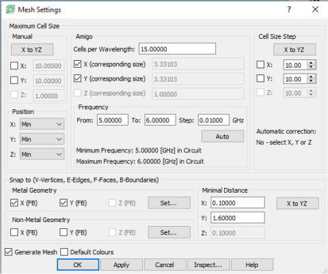
At this stage we should define the mesh. To do that, in Model tab we press the Settings button. The following dialogue will appear.
In this example we will use automatic meshing option (AMIGO - Automatic Meshing Intelligent Generation Option). We set 15 cells per wavelength in both directions and uncheck Snap to Non-Metal Geometry boxes. We set Minimal Distance between snapping planes along the Y axis to 1.6 mm.
In the Model tab we press the Borders button. The Boundary Conditions dialogue will appear.
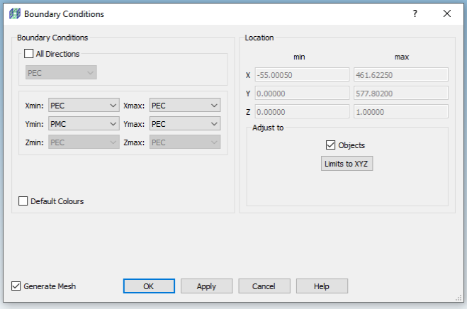
In the Boundary conditions frame we uncheck the All directions check box and we set Perfect Magnetic Conductor (PMC) for Ymin position and Perfect Electric Conductor (PEC) for the rest and press OK.
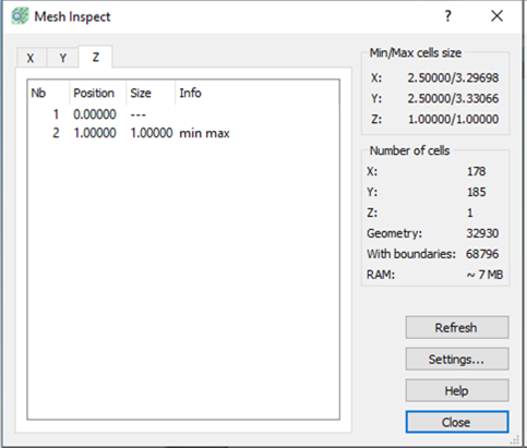
The information about FDTD mesh in each direction can be viewed in the Mesh Inspect dialogue.