18.4Drawing the ports
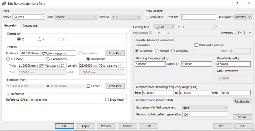
In the next step of preparing this project we proceed to drawing and configuring the exciting port. For that purpose we switch to Model tab, press Transmission Line button and choose Insert Transmission Line Source option. We need to place the port in the waveguide - as it has its beginning at x = QW V ars.wg pos = −10mm, we should set Position X respectively. To adjust port dimensions to the waveguide’s inside, we should select Dimensions option and set Length parameter to QW Vars.wg r and Ymid parameter to QW Vars.wg r/2.
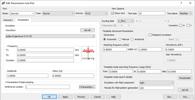
Then we switch to Parameters tab in Create Transmission Line Port dialogue to set up the port parameters. We excite the antenna with circular TEn1 mode, where n is angular variation defined for the project, in the frequency range from 5 to 6 GHz. The port settings are shown in picture below and we accept them by pressing OK button.