
1.2.1 Normal incidence of a plane wave on the two lossless dielectric media boundary
Model considered herein works at 5GHz, which according to IEEE 802.11 specification, is a wireless communication frequency. The wave propagates in air, incidents on a concrete wall and further propagates in this medium. The reflection coefficient, SWR, reflected and transmitted power will be determined. Theoretical calculations will be compared with the simulation results.
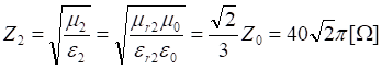
The parameters of a concrete wall are assumed as follows: εr2=4.5, μr2=1, σ=0.
Characteristic impedances of the two media are calculated as:
Thus the reflection coefficient equals:
![]()
Negative value of the reflection coefficient means that the wave propagates from a medium of higher impedance.
Standing wave ratio in a first medium is calculated as follows:
![]()
The calculated value indicates that the wave in first medium is more like a traveling wave than a standing wave.
The above parameters should be now extracted from the simulation results. Start simulation of the ppw5.QWpro scenario using ![]() button in Simulation tab. Open 1D visualization window by clicking
button in Simulation tab. Open 1D visualization window by clicking ![]() button in 1D Fields tab. Switch to existing field component i.e. Hy. The media boundary should be clearly visible (
button in 1D Fields tab. Switch to existing field component i.e. Hy. The media boundary should be clearly visible (![]() ). If not, adjust the scale using Scaling dialogue available with Alt + S keyboard combination. Place markers at the envelope maximum and minimum according to standing wave ratio definition. Standing wave ratio can be now calculated automatically using Attn button in Function tab of 1D Fields window. The SWR value is visible in Markers tab.
). If not, adjust the scale using Scaling dialogue available with Alt + S keyboard combination. Place markers at the envelope maximum and minimum according to standing wave ratio definition. Standing wave ratio can be now calculated automatically using Attn button in Function tab of 1D Fields window. The SWR value is visible in Markers tab.
The window display including markers positions is shown in Fig 14.

Fig 14 Magnetic field Hy element envelope and temporary waveform (example).
The value of SWR calculated from simulation data is very close to the theoretical value. Based on that value, the reflection coefficient can be calculated as follows:
![]()
The above formula allows calculating an absolute value of the G coefficient. To determine the sign of reflection coefficient, the fields' envelope must be observed. If the magnetic field envelope takes maximum value at the media boundary (and respectively, envelope of electric field takes minimum) the wave propagates from a medium of higher impedance (to medium of lower impedance) and the sign of reflection coefficient is minus. If opposite the sign is plus.
Power reflected from the concrete wall will be now calculated. Assuming that the concrete wall reflects G of electric field and G of magnetic field, the reflected power is proportional to G2:
![]()
This means that 13% of a plane wave power is reflected from the concrete wall and 87% is transmitted further through a concrete material.