

|
|

5.1 Circuit Settings
The Circuit buttonin Model tab invokes Circuit Settings dialogue. The options available in this dialogue are arranged in three tabs, Basic, Circuit Type, and Advanced.
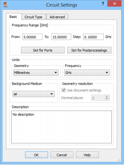
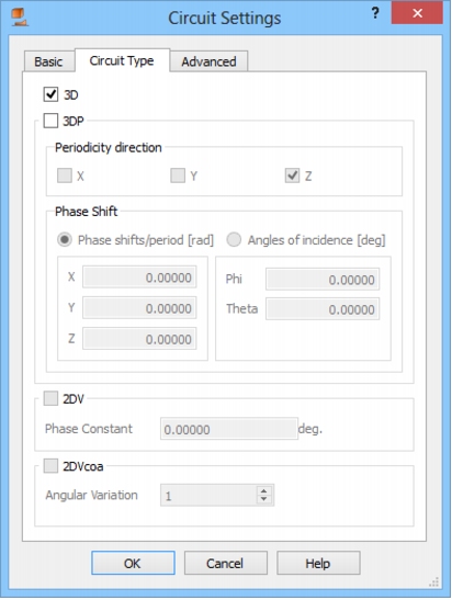
 In the Basic tab the user specifies the frequency band of interest. If the defined range is the same as the excitation frequency range and should be also used for postprocessings calculations the user can assign it automatically by pressing Set for Ports and Set for Postprocessings buttons respectively. Further, the Background Medium and the Units used in the project can be set.Circuit Type tab allows determining the type of the circuit that will be analysed. In the current version of QW-Modeller, the user can choose either it will be typical three-dimensional (3D) or 3D periodic (3DP) scenario. In case of 3DP projects it is necessary to set the Periodicity direction (determine at which boundaries the periodic boundary conditions will be imposed), by checking appropriate axes and defining the Phase shifts. There are two ways of doing that. Firstly, it can be done explicitly by defining the Floquet Phase shifts per period in radians. This option is set as default and the Floquet phase shifts can be easily calculated using the following formulae:
(1)
(2)
(3)
where φ and θ are the spherical coordinates with Z reference axis, Li is a spatial period of the structure along i axis and c stands for the light velocity. In the second option the user can define the incidence angles of the illuminating wave (Angles of incidence), directly by setting the values of φ and θ in degrees.In the future versions of QW-Modeller, 2DVcoa circuits, denoting axisymmetrical structures (two-dimensional in cylindrical coordinates) and 2DV circuits, usable for guided problems with a known phase constant (drawn as a two-dimensional structure in XY plane) will be enabled.
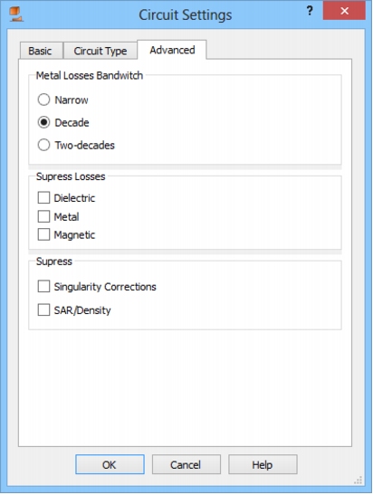
In the Advanced tab we can find Metal Losses Bandwidth choices, which regards the bandwidth for rigorous consideration of frequency-dependent skin effect in lossy metals. It has to be pointed out that although the description of losses in metals by finite conductivity is essentially the same as that of lossy dielectrics, the level of conductivity makes a very significant difference. Due to very high conductivity the wavelength becomes so short that it is practically impossible to mesh the lossy metal volume. Thus instead, in QW-3D we virtually attach lossy elements to the magnetic field components tangential to the metal surface. To reproduce the frequency dependence, we attach to each of the tangential magnetic field components an RL ladder composed of a finite number (K) of cells. With the number K increasing we can model accurately the skin effect in a wider band, but at the price of increasing computer time and memory. That is why we allow the user to make the choice of the model to be used. The three options: Narrow, Decade and Two Decades correspond to the number K varying from 2 to 12, with appropriate change in wide band properties of the model. The central frequency for the band is taken as: in the case of sinusoidal excitation - frequency of the source; in the case of pulse excitation - central frequency of the band of postprocessing; in the case of pulse excitation and no postprocessing - 10 GHz.There are also five suppress options, for suppressing dielectric, metal or magnetic losses, singularity corrections, and SAR analysis. Suppressing the losses saves memory and computing time. Thus it is very convenient when we want to obtain faster preliminary simulation results without laborious modification of the entire project. Suppressing singularity corrections is only used in specific software operation, evaluating the influence of field singularities on the accuracy of FDTD results.
Python codeThe python code, which can be useful when creating project scripts, generated by Circuit Settings dialogue for default parameters:
App.ActiveDocument.QW_MediaLibrary.BackgroundMedium = "air"App.ActiveDocument.QW_Circuit.FreqencyFrom = 5.00000App.ActiveDocument.QW_Circuit.FreqencyTo = 15.00000App.ActiveDocument.QW_Circuit.FreqencyStep = 0.10000App.ActiveDocument.QW_Circuit.Units = "mm"App.ActiveDocument.QW_Circuit.FrequencyUnits = "GHz"App.ActiveDocument.QW_Circuit.Description = "No description"App.ActiveDocument.QW_Circuit.CircuitType = "3D"App.ActiveDocument.QW_Circuit.PeriodicityX = FalseApp.ActiveDocument.QW_Circuit.PeriodicityY = FalseApp.ActiveDocument.QW_Circuit.PeriodicityZ = TrueApp.ActiveDocument.QW_Circuit.PhaseShiftType = "Phase shift/period"App.ActiveDocument.QW_Circuit.PhaseShiftX = 0.00000App.ActiveDocument.QW_Circuit.PhaseShiftY = 0.00000App.ActiveDocument.QW_Circuit.PhaseShiftZ = 0.00000App.ActiveDocument.QW_Circuit.Phi = 0.00000App.ActiveDocument.QW_Circuit.Theta = 0.00000App.ActiveDocument.QW_Circuit.PhaseConstant = 0.00000App.ActiveDocument.QW_Circuit.AngularVariation = 1App.ActiveDocument.QW_Circuit.MetalLossesBandwidth = "Decade"App.ActiveDocument.QW_Circuit.SuppressLossesDielectric = FalseApp.ActiveDocument.QW_Circuit.SuppressLossesMetal = FalseApp.ActiveDocument.QW_Circuit.SuppressLossesMagnetic = FalseApp.ActiveDocument.QW_Circuit.SuppressSingularityCorrections = FalseApp.ActiveDocument.QW_Circuit.SuppressDensity_SAR = False
|
QWED Sp. z o.o. Voice: +48 22 625 73 19 Fax: +48 22 621 62 99 info@qwed.eu |
|
|