

|
|

4.4 Setting up the mesh
The structure and all the required simulation objects have been introduced thus, we can now define the meshing. In the Mesh Settings dialogue, available under Settings button, we set the global cell size to 0.5 mm, 0.5 mm, and 1 mm in the X, Y, and Z direction, respectively. We accept the settings by pressing OK button and the meshing is generated.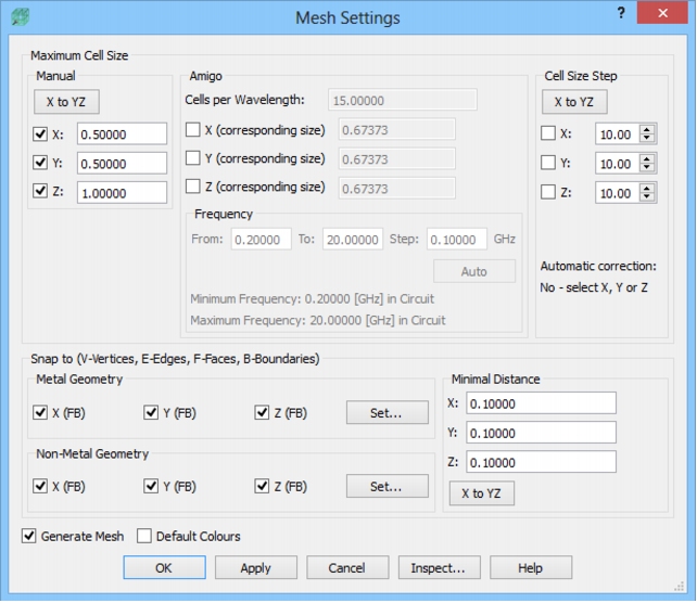 Mesh Settings dialogue for the microstrip line filter project.
In case of planar structures it is required to dense the meshing in the strip neighbourhood (above and under). The tool that was destined for that purpose is called Mesh Box. To insert the Mesh Box into the project we press Snap button in the Model tab and choose Mesh Box option.
The Mesh Box configuration is divided into two stages. Firstly we need to define its dimensions and secondly cell size and the directions in which it should be enforced. In this case we want the Mesh Box to have the length and width of the substrate and the height of 2.5 mm, which will extends sufficiently above the strip. The picture below shows the dimensions' settings for the Mesh Box, where we choose the Coordinates option to define them.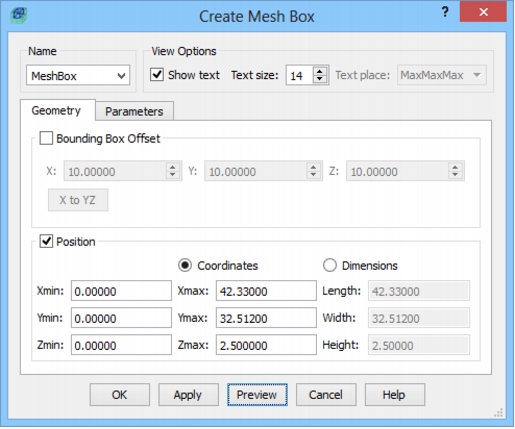 Create Mesh Box dialogue with Geometry tab settings.
We can now define the required cell size inside the Mesh Box. For that purpose we need to switch to the Parameters tab in Create Mesh Box dialogue. Since we do not need to dense the meshing in the strip plane we indicate that the meshing should be modified only in the Z direction and we set the cell size to 0.3 mm. We accept all the settings by pressing OK button.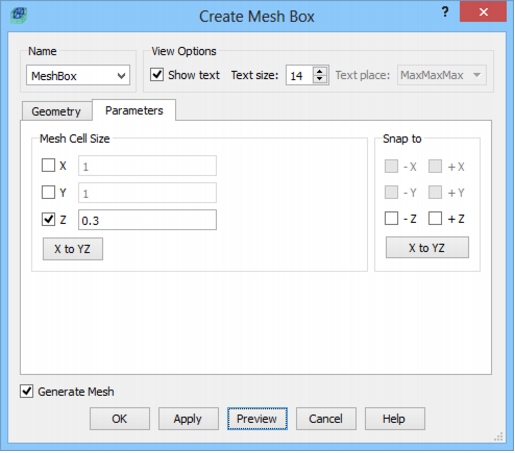 Create Mesh Box dialogue with Parameters tab settings.
After pressingbutton in the Mesh section, the mesh will be generated.
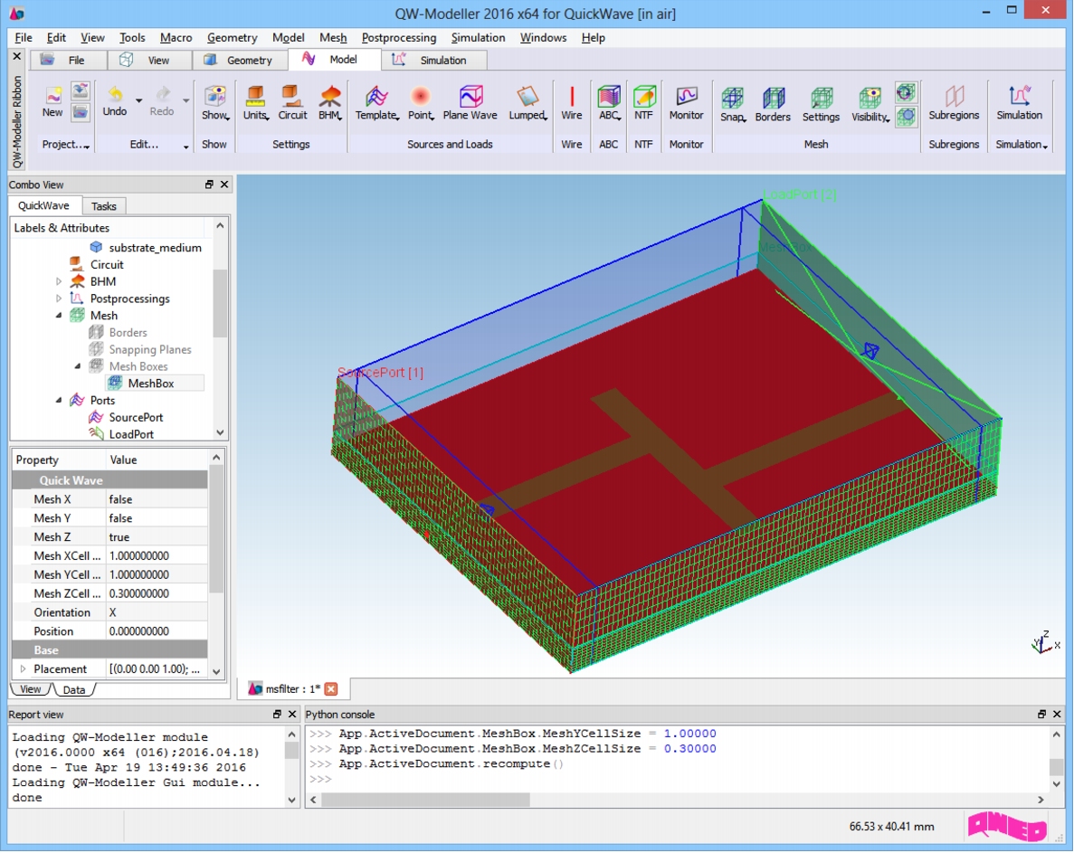 Microstrip filter project with meshing.
|
QWED Sp. z o.o. Voice: +48 22 625 73 19 Fax: +48 22 621 62 99 info@qwed.eu |
|
|