Circular waveguide discontinuity (V2D BOR)
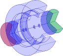
The present example considers a circular waveguide discontinuity (V2D BOR).
Circular waveguide discontinuity (V2D BOR).
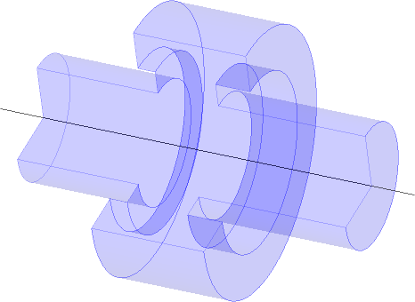
The structure that is analysed herein is an axisymmetrical waveguide with discontinuity. Axial symmetry allows for performing the waveguide analysis with ultra-fast vector 2D Bessel and FDTD hybrid solver (V2D BOR) designated for Bodies of Revolution (BOR) structures. This solver allows for analysing only half of structure's long-section, which results in its extremely fast performance. The structure should be drawn in a way that its symmetry axis coincides with project symmetry axis ρ=0 (in the QW-Editor and QW-Simulator referred as y=0).
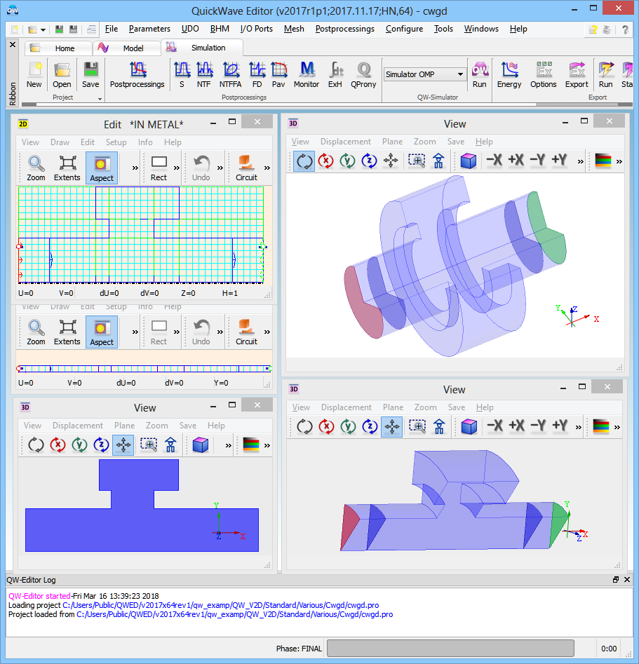
Circular waveguide discontinuity (V2D BOR) project in QW-Editor.
Simulation model assumes that at both ends of the waveguide, the transmission line ports are placed. On the right, we placed an input port, exciting circular waveguide fundamental TE11 mode. On the left end, the waveguide is terminated with an output port, that is matched to the structure.
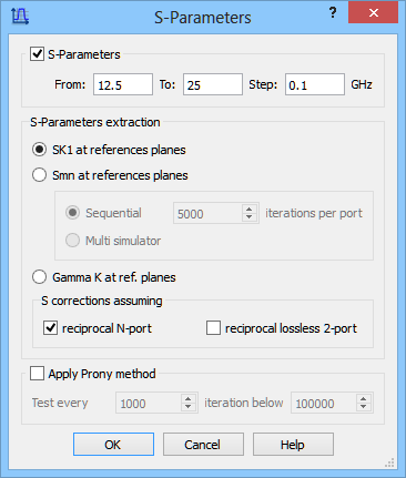
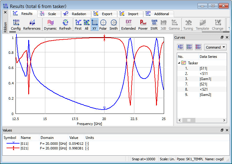
For this scenario, we are interested in calculating reflection and transmission characteristics. For that purpose, S-Parameters postprocessing is activated in a frequency range from 12.5 GHz to 25 GHz, with a frequency step of 0.1 GHz.
S-Parameters postprocessing configuration dialogue.
Reflection and transmission characteristics of the considered circular waveguide.
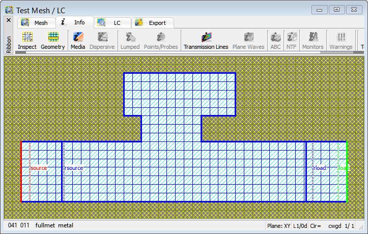
Effective FDTD mesh display - only one layer of a half of structure’s long-section.
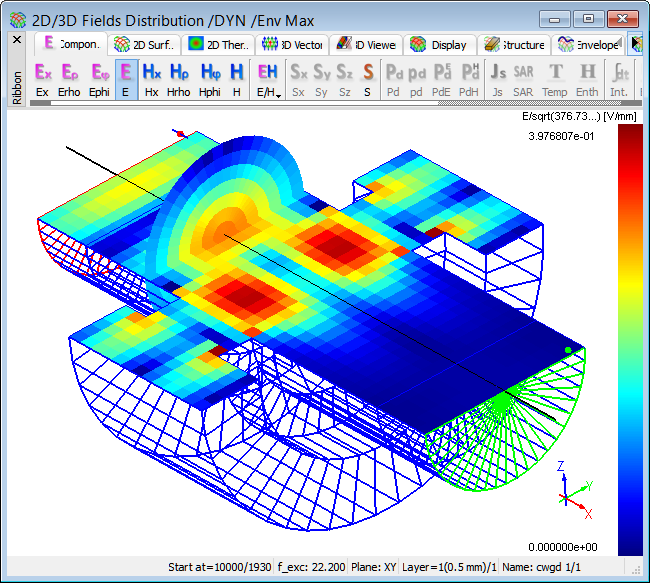
Distribution of time-maximum envelope of total E field at 20 GHz.
Distribution of time-maximum envelope of total E field at 22.2 GHz.